MDR-2000 VJ User's Reference Manual
Hardware
7.2 Cables
The
MDR-2000
is designed to connect directly to a
PBX
through use
of
the
MDR-2000
PBX
port,
and directly to a
modem
using the
MDR-2000
modem
port. For this reason the
PBX
port
is wired
as a serial terminal (
DTE
) and the
modem
port as a
modem
(DCE). The following paragraphs
describe
the
cabling required for the two ports under
diff
erent circumstances.
The
cable
from
the
PBX
to the
MDR-2000
is provided by the local telephone equipment supplier.
The
connector
made
available for use
on
the
MDR-2000
must be a male
DB25-P
EIA connector
with pins labeled 1 through 25. This is the
most
commonly used connector configuration for EIA
RS232-C
interfaces.
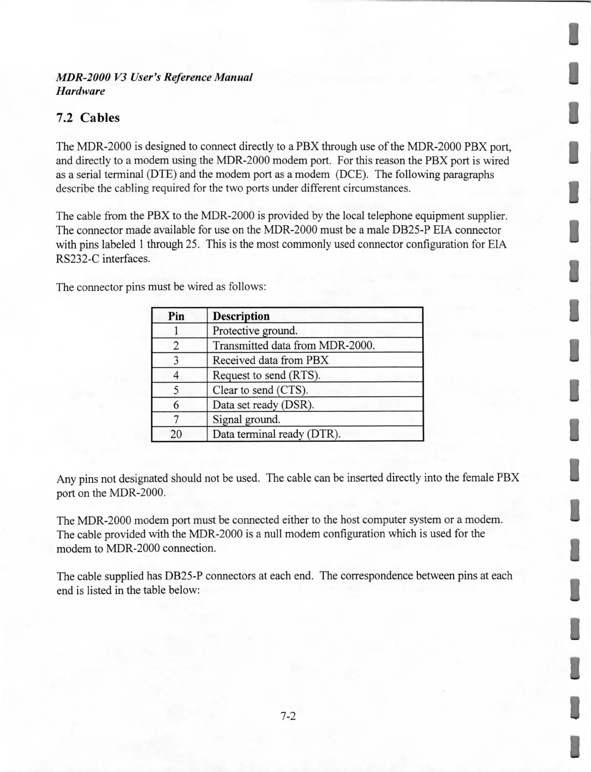
The
connector pins
must
be wired as follows:
Pin Description
1
Protective ground.
2
Transmitted data from MDR-2000.
3
Received
data
from
PBX
4
Request to send (RTS
).
5
Clear to send (CTS).
6
Data
set ready (DSR).
7
Signal ground.
20
Data
terminal ready (
DTR
).
Any
pins
not
designated should not be used.
The
cable
can
be inserted directly into the female
PBX
port
on
the
MDR-2000
.
The
MDR-2000
modem
port
must
be connected either to the host computer system
or
a
modem
.
The
cable provided with the
MDR-2000
is a null
modem
configuration
which
is
used
for the
modem
to
MDR-2000
connection.
The
cable supplied has DB25-P connectors at
each
end
.
The
correspondence
between
pins at each
end is listed in the table below:
7-2
I
 Loading...