Do you have a question about the MDV CTBU-09HWFN1-MC and is the answer not in the manual?
Instructions to prevent injury to users and property damage.
Important warnings regarding installation and operation.
Lists model names for indoor and outdoor units based on series and capacity.
Identifies and labels parts of indoor and outdoor units with diagrams.
Details the specific features and functionalities of various unit types.
Describes features specific to A5 Duct units, including installation accessories and maintenance.
Lists optional accessories for A5 Duct unit installation.
Explains the dual air inlet options for A5 Duct units for flexible installation.
Details the fresh air intake feature for improved indoor air quality.
Describes procedures for easy cleaning and maintenance of the filter and components.
Explains the ports for connecting remote or central control systems.
Describes the optional built-in drain pump for condensate water management.
Covers the functionality of the built-in display board for error codes and remote control.
Details features specific to Cassette Units, focusing on noise reduction and modes.
Explains design optimizations for reduced noise levels in cassette units.
Describes the optional turbo mode for rapid cooling or heating.
Highlights the redesigned, fire-resistant controller box for enhanced safety.
Mentions the fresh air intake function for improved air quality.
Discusses the benefits of an optional wired controller for commercial applications.
Details the built-in drain pump for condensate water lifting capability.
Describes standard terminals for alarm lamps and remote on-off controllers.
Covers features and design aspects of Console Units.
Highlights the aesthetic design of console units for living spaces.
Mentions the availability of optional four-panel configurations for console units.
Explains the two air outlet modes (Quick Cooling, Maintain Room Temp) for console units.
Shows the console unit with four air inlets.
Details features contributing to low noise operation, like DC fan motor and advanced fan technology.
Notes the optional golden fin feature.
States that an active carbon filter is a standard component.
Describes features of Ceiling-floor Units, including installation and design.
Explains the dual installation options (ceiling or floor-level) for flexibility.
Highlights the brief design suitable for various interiors.
Details the 3D airflow adjustment for even air distribution in large rooms.
Describes optional drainage pipe connections on both sides for installation convenience.
Covers convenience in operation and ease of maintenance, including filter access.
Highlights features that simplify installation and save time, like flexible pipe connection.
Mentions the optional outside water pump for ceiling installations.
Details features specific to A6 Duct Units, including static pressure and design.
Describes the unit's medium static pressure capability and wide static pressure range.
Highlights the industry-lowest height design for installation in tight roof spaces.
Explains the technology for automatically adjusting air volume based on static pressure.
Lists optional installation accessories for A6 Duct units.
Explains the flexibility in choosing air intake direction for different applications.
Describes the simplified, error-resistant communication wire connection for A6 duct units.
Details features for easy cleaning of filters and internal components.
Explains how A6 duct units facilitate easier maintenance access for motors and internal parts.
Describes the twin system that connects two indoor units to one outdoor unit for wider air distribution.
Explains the optional fresh air intake function to improve indoor air quality.
Mentions the optional built-in drain pump for condensate water management.
Details features of HESP DUCT units, focusing on static pressure and application.
Highlights the high static pressure capability and long air supply distance, suitable for large spaces.
Describes the easy maintenance access for HESP DUCT units.
Explains flexible installation using various air distribution duct solutions for different room shapes.
Describes the ease of removing and installing the filter from the rear side for cleaning.
Provides dimensional specifications for various indoor unit types, including A5 Duct units.
Displays detailed dimensions and connection points for cassette units of specific capacities.
Provides dimensional data and connection points for larger capacity cassette units.
Shows the dimensions and mounting details for console unit indoor units.
Presents dimensional information and mounting parameters for ceiling-floor type indoor units.
Displays dimensional specifications for A6 Duct indoor units across different capacities.
Provides detailed dimensions and mounting points for the MHG-60HWFN1-MW unit.
Presents dimensional specifications for various outdoor unit models, including dimensions W, D, H, W1, A, B.
Shows dimensions and weight specifications for specific outdoor unit models.
Specifies the required service space for indoor unit installation and maintenance for different types.
Details the service space requirements around console units for installation and maintenance.
Outlines the necessary clearance space for ceiling-floor units.
Specifies the required maintenance and repair space for HESP DUCT units.
Defines the necessary clearances around the outdoor unit for proper airflow and service.
Illustrates the refrigerant flow for specific indoor/outdoor unit combinations.
Shows the refrigerant cycle diagram for specific outdoor unit models.
Provides wiring diagrams for various indoor unit models, detailing connections and components.
Presents the indoor unit wiring diagram for specific CFAU models.
Shows the indoor unit wiring diagram for specific MCD models.
Displays wiring diagrams for CTBU indoor units of 36K and 48K models.
Provides wiring diagrams for MUEU indoor units of 18K and 24K capacities.
Shows the wiring diagram for the MUE-36HRFN1-M(C) indoor unit.
Presents the wiring diagram for the MUE-48HRFN1-M(C) indoor unit.
Displays the wiring diagram for the MUE-60HRFN1-MW indoor unit.
Shows DIP switch settings and function indications for MUE units.
Details DIP switch settings and indications for the MUE-60HRFN1-MW unit.
Presents wiring diagrams and DIP switch settings for MTI/MTIU indoor units.
Displays wiring diagrams and DIP switch settings for MTIU/MHG indoor units.
Provides wiring diagrams for various outdoor unit models, detailing PCB connections.
Shows the outdoor unit wiring diagram and notes for specific MOBA/MOB models.
Presents outdoor unit wiring diagrams with component descriptions for specific MOD models.
Displays the outdoor unit wiring diagram and notes for the MOD30U-36HFN1-M model.
Provides outdoor unit wiring diagrams and PCB board details for specific MOE models.
Illustrates the IPM board layout and connections for specific outdoor unit models.
Details the PCB layout for specific MOBA/MOB outdoor units.
Shows the PCB layout for specific MOE outdoor units.
Illustrates the IPM board layout and connections for specific outdoor unit models.
Presents a table of static pressure values for different models and fan speed settings.
Displays fan curves showing external static pressure vs. air volume for CTBU-09HWFN1-M(C) at different codes.
Shows fan curves for CTBU-12HWFN1-M(C), relating static pressure to air volume for various codes.
Presents fan performance curves for CTBU-18HWFN1-M(C) across different operating codes.
Displays fan curves for CTBU-24HWFN1-M(C), illustrating static pressure vs. air volume for various codes.
Shows fan curves for CTB-36HWFN1-M(C), detailing static pressure against air volume for different codes.
Presents fan performance curves for CTB-48HWFN1-M(C), relating static pressure to air volume across codes.
Displays fan curves for MHG-60HWFN1-MW at high and low speeds, showing static pressure vs. air volume.
Lists electric characteristics such as voltage and frequency for various indoor unit models.
Provides indoor unit sound level data (dB(A)) in H, M, L modes for concealed duct types.
Lists indoor unit sound levels (dB(A)) for CCA3U series in H, M, L modes.
Shows indoor unit sound levels (dB(A)) for CFAU models in H, M, L modes.
Provides indoor unit sound level data (dB(A)) for MUBU and MUEU series in H, M, L modes.
Lists outdoor unit sound levels (dB(A)) for various models.
Lists accessories included for duct units, categorized by type.
Lists accessories provided for cassette units, including installation fittings and remote controls.
Details accessories for console units, such as mounting screws, batteries, and manuals.
Lists accessories for ceiling-floor units, including remote controllers and manuals.
Details power specifications, including phase, voltage, circuit breaker ratings, and wiring requirements.
Provides guidelines for selecting appropriate indoor and outdoor unit installation locations.
Specifies criteria for choosing the best location for indoor unit installation.
Lists considerations for selecting an optimal location for the outdoor unit.
Guides the installation process for A5 and A6 duct indoor units.
Details the required clearance space around A5/A6 duct indoor units for installation.
Shows bolt pitch dimensions for mounting A5/A6 duct indoor units.
Provides step-by-step instructions for hanging the indoor unit, including drilling and securing.
Guides the installation of ducts and related accessories for A5 Duct units.
Details the installation procedure for compact cassette indoor units.
Specifies the required service space for compact cassette indoor units.
Shows the bolt pitch for compact cassette indoor unit mounting.
Explains how to install pendant bolts for compact cassette units.
Guides the installation of the main body of the compact cassette unit.
Provides steps for installing the panel of a compact cassette unit, including grille and cover removal.
Details the installation process for console indoor units.
Specifies the required service space for console indoor units.
Guides the installation of the main body of console units.
Outlines the installation steps for ceiling-floor units.
Specifies the service space requirements for ceiling-floor indoor units.
Shows bolt pitch dimensions for ceiling installation of ceiling-floor units.
Explains how to install pendant bolts for ceiling-floor units.
Guides the installation of the main body for ceiling-floor units.
Details the installation procedure for slim cassette indoor units.
Specifies the required service space for slim cassette indoor units.
Shows bolt pitch dimensions for slim cassette indoor units.
Explains how to install pendant bolts for slim cassette units.
Guides the installation of the main body for slim cassette units.
Provides steps for installing the panel on slim cassette units.
Details the installation procedure for HESP duct indoor units.
Specifies the service space requirements for HESP duct indoor units.
Shows bolt pitch dimensions for HESP duct units.
Explains how to install pendant bolts for HESP duct units.
Guides the installation of the main body for HESP duct units.
Provides recommendations for designing and installing air ducts for HESP duct units.
Covers the overall process of installing the outdoor unit.
Specifies the required clearances around the outdoor unit for proper operation and service.
Shows bolt pitch dimensions for outdoor unit mounting.
Provides instructions for safely lifting and installing the outdoor unit.
Details the process of installing refrigerant pipes, including length and height considerations.
Specifies the maximum allowable pipe length and height difference for refrigerant lines.
Outlines the steps for connecting refrigerant pipes, including cutting and flaring.
Covers the critical first-time installation steps, including air and moisture removal from the refrigerant system.
Explains the procedure for vacuum drying the system using a vacuum pump.
Details the process of purging air using refrigerant.
Guides on adding refrigerant for systems that have been operated for a long time.
Outlines steps for re-installation when an indoor unit needs repair.
Provides guidelines for installing the drainage pipe and preventing issues.
Covers key principles for drainage pipe installation, including slope and diameter.
Highlights important considerations for drainage pipe installation, like route and material selection.
Explains how to set water storage pipes to prevent converse flow or water blow phenomena.
Details pipe settings for indoor units with water pumps, considering pump head.
Describes the importance of blowhole settings for drainage systems.
A specific instruction regarding the drainage pipe's end point.
Outlines procedures for drainage system testing, including water leakage and discharge tests.
Refers to insulation engineering for drainage pipes.
Explains the purpose and methods for vacuum drying and checking for leaks.
Details the reasons for vacuum drying, such as preventing ice-blockage and oxidation.
Provides specifications for selecting an appropriate vacuum pump.
Describes the operational procedures for vacuum drying, including ordinary and special methods.
Explains the standard procedure for vacuum drying a system.
Describes special vacuum drying methods for specific conditions.
Details the process of calculating and performing additional refrigerant charges.
Covers the operational procedures, purpose, and material selection for refrigerant pipe insulation.
Covers the operational procedures, purpose, and material selection for refrigerant pipe insulation.
Discusses insulation material selection and installation highlights for drainage pipes.
Outlines key aspects of electrical wiring installation, including safety and regulations.
Outlines key aspects of electrical wiring installation, including safety and regulations.
Describes the procedure for conducting test operations after installation.
Lists essential checks to perform before initiating test operations.
Details the steps for conducting the actual test operation of the unit.
Explains the operating characteristics of the air conditioner under different temperature conditions.
Defines abbreviations used for various temperature sensors and parameters.
Explains the icons and display functions on the indoor unit's display board for different unit types.
Details the main protection functions and error codes for the unit.
Explains the 3-minute delay mechanism for compressor restarts.
Describes the protection mechanism for compressor top temperature.
Details protection measures for compressor discharge temperature, including frequency limits.
Explains the unit's response to indoor and outdoor fan speed malfunctions.
Covers protection functions related to current, voltage, and temperature for the inverter module.
Explains the delayed opening of the indoor fan and its interaction with anti-cold wind function.
Details the compressor preheating function, its conditions, and modes of operation.
Explains the protection mechanism triggered by high condenser temperatures.
Describes the protection triggered by low evaporator temperatures.
Explains the operation modes of the air conditioner, including fan, cooling, heating, and auto modes.
Explains the fan mode operation, including indoor fan speed control and auto fan behavior.
Details the outdoor and indoor fan running rules during cooling mode.
Describes the outdoor and indoor fan running rules during heating mode.
Explains the conditions for entering defrosting mode and how it ends.
Describes the auto mode operation, including temperature settings and mode selection logic.
Explains the drying mode operation, which is similar to cooling mode.
Details the functionality of the timer for setting on/off times.
Explains the sleep function, including temperature adjustments and fan speed settings.
Describes the auto-restart feature that resumes previous settings after a power failure.
Explains the "Follow me" function that allows the unit to adjust based on remote controller temperature.
Details the optional 8℃ heating function for maintaining room temperature in cold weather.
Explains how the drain pump is controlled by the water-level switch.
Describes how to access and interpret various operational data points using the remote controller.
Lists the types of enquiry information available and their corresponding display codes and meanings.
Provides safety precautions for troubleshooting, especially concerning capacitor discharge.
Lists indoor unit error codes, corresponding displays, and LED status indicators.
Details outdoor unit error displays and LED indications for 9K-24K units.
Lists outdoor unit error codes for 36K-60K models.
Explains how to use the outdoor unit's check function to display operational data.
Describes the display values and remarks for various outdoor unit check functions.
Provides diagnosis and solutions for common error codes and malfunctions.
Provides diagnosis and solutions for EEPROM parameter errors.
Details troubleshooting steps for communication errors between indoor and outdoor units.
Provides remarks on using a multimeter for voltage tests and reactor resistance checks.
Outlines troubleshooting steps for communication malfunctions in 36K-48K units.
Provides diagnosis and solutions for fan speed malfunction errors.
Explains how to measure DC motor voltage input and output for troubleshooting.
Offers diagnosis and solutions for temperature sensor circuit errors.
Provides troubleshooting steps for refrigerant leakage detection errors.
Details diagnosis and solutions for water-level alarm malfunctions.
Offers diagnosis and solutions for IPM malfunction and over-current protection.
Shows multimeter readings for P-U voltage measurement.
Illustrates multimeter readings for P-V voltage measurement.
Shows multimeter readings for P-W voltage measurement.
Illustrates multimeter readings for P-N voltage measurement.
Provides diagnosis and solutions for over-voltage or under-voltage protection issues.
Details diagnosis and solutions for high temperature protection of the compressor top.
Offers diagnosis and solutions for high temperature protection of the IPM board.
Provides diagnosis and solutions for inverter compressor drive errors.
Details diagnosis and solutions for outdoor IPM module temperature sensor malfunctions.
Explains the J0 malfunction related to evaporator coil temperature and provides troubleshooting steps.
Details the J1 malfunction related to outdoor pipe temperature and provides troubleshooting steps.
Explains the J2 malfunction related to compressor discharge temperature and provides troubleshooting.
Details the J3 malfunction related to PFC module protection and provides troubleshooting.
Explains the J4 malfunction related to communication errors and provides troubleshooting steps.
Details the J5 malfunction related to high pressure protection and provides troubleshooting.
Explains the J6 malfunction related to low pressure protection and provides troubleshooting.
Details the J8 malfunction related to abnormal voltage and provides troubleshooting.
Provides methods for checking main components like temperature sensors.
Describes how to check temperature sensors by measuring resistance with a tester.
A table listing temperature sensor resistance values at different temperatures.
A table showing resistance values for T5 and TH temperature sensors at various temperatures.
A table listing temperature values in Celsius and Fahrenheit, likely for reference.
Presents cooling mode pressure charts showing relationships between indoor and outdoor temperatures.
Displays heating mode pressure charts relating indoor and outdoor temperatures.
Provides instructions for disassembling the indoor unit.
Details disassembly steps for the A5 Duct indoor unit, covering electronic control box, PCB, and fan.
Outlines disassembly procedures for cassette units, including filter, panel, and display board removal.
Specific step for removing the grille on cassette units.
Steps for disassembling the display board of cassette units.
Instructions for removing the swing motor assembly from cassette units.
Details the process of removing the PCB from cassette units.
Instructions for removing the electronic control box from cassette units.
Steps for removing the fan wheel from cassette units.
Provides instructions for removing the fan motor from cassette units.
Details the process of removing the water collecting assembly from cassette units.
Instructions for removing the draining pump from cassette units.
Steps for removing the evaporator from cassette units.
Provides disassembly instructions for console units.
Steps for removing the filter from console units.
Instructions for removing the electronic control box from console units.
Details the process of removing the PCB from console units.
Steps for removing the display board from console units.
Instructions for removing the switch board from console units.
Steps for removing the air outlet grille assembly from console units.
Instructions for removing the louver motor assembly from console units.
Details the removal of the louver motor from the water collector in console units.
Steps for removing the water collector from console units.
Instructions for removing the evaporator assembly from console units.
Steps for removing the centrifugal fan from console units.
Provides instructions for removing the fan motor from console units.
Provides disassembly instructions for A6 Duct units.
Steps for removing the electronic control box from A6 Duct units.
Details the process of removing the PCB from A6 Duct units.
Instructions for removing the reactance component from A6 Duct units.
Steps for removing the drain pump from A6 Duct units.
Instructions for removing the fan motor from A6 Duct units.
Details the process of removing the water collector assembly from A6 Duct units.
Steps for removing the evaporator from A6 Duct units.
Provides disassembly instructions for specific MOB outdoor units.
Steps for removing the panel plate from MOB outdoor units.
Instructions for removing the fan assembly from MOB outdoor units.
Details the removal of electrical parts from MOB outdoor units.
Steps for removing the four-way valve from MOB outdoor units.
Instructions for removing the compressor from MOB outdoor units.
Provides disassembly instructions for MOCA outdoor units.
Steps for removing the panel plate from MOCA outdoor units.
Instructions for removing the fan assembly from MOCA outdoor units.
Details the removal of electrical parts from MOCA outdoor units.
Steps for removing the four-way valve from MOCA outdoor units.
Instructions for removing the compressor from MOCA outdoor units.
Provides disassembly instructions for MOD outdoor units.
Steps for removing the panel plate from MOD outdoor units.
Instructions for removing the fan assembly from MOD outdoor units.
Details the removal of electrical parts from MOD outdoor units.
Steps for removing the four-way valve from MOD outdoor units.
Instructions for removing the compressor from MOD outdoor units.
Provides disassembly instructions for specific MOD outdoor units.
Steps for removing the panel plate from MOD outdoor units.
Instructions for removing the fan assembly from MOD outdoor units.
Details the removal of electrical parts from MOD outdoor units.
Steps for removing the four-way valve from MOD outdoor units.
Instructions for removing the compressor from MOD outdoor units.
Provides disassembly instructions for specific MOE outdoor units.
Steps for removing the fan assembly from MOE outdoor units.
Instructions for removing the panel plate from MOE outdoor units.
Details the removal of electrical parts from MOE outdoor units.
Steps for removing the four-way valve from MOE outdoor units.
Instructions for removing the compressor from MOE outdoor units.
Final steps for removing wires and the electronic control box.
Instructions for removing the PCB board.
Provides disassembly instructions for specific MOD outdoor units.
Steps for removing the panel plate from MOD outdoor units.
Instructions for removing the fan assembly from MOD outdoor units.
Details the removal of electrical parts from MOD outdoor units.
Steps for removing the four-way valve from MOD outdoor units.
Instructions for removing the compressor from MOD outdoor units.
Provides disassembly instructions for specific MOE outdoor units.
Steps for removing the fan assembly from MOE outdoor units.
Instructions for removing the panel plate from MOE outdoor units.
Details the removal of electrical parts from MOE outdoor units.
Steps for removing the IPM board from MOE outdoor units.
Instructions for disconnecting connectors and wires from the PCB.
Steps for removing the compressor from MOE outdoor units.
Instructions for removing the 4-way valve from MOE outdoor units.
Steps for removing the expansion valve from MOE outdoor units.
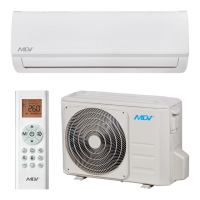
| Model | MDV CTBU-09HWFN1-MC |
|---|---|
| Cooling Capacity | 9000 BTU/h |
| Energy Efficiency Ratio (EER) | 3.21 |
| Refrigerant | R410A |
| Weight (Indoor Unit) | 8 Kg |
| Operating Temperature (Heating) | -7-24°C |
| Type | Split |
| Heating Capacity | 9500 BTU/h |
| Power Supply | 220-240V/50Hz |
| Operating Temperature (Cooling) | 18-43°C |
| Outdoor Unit Noise Level | 50 dB |