GB
17
ENGLISH
LEGEND
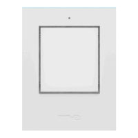
1 = Doorbell button (KTF-3 is illustrated)
2 = Brightness sensor
3 = Nameplate(s)
4 = Housing screws
5 = Mounting holes
6 = Doorbell button on the circuit board
7 = Connection terminals
8 = Nameplate illumination
9 = Cable entry
INSTALLATION
Note: The installation location should be as at as possible to avoid warping the
housing during installation. If an external power supply is used, the connection
wires should be centrally located in the lower third behind the doorbell button.
Opening the Housing
Open the doorbell button by unscrewing the housing screws (4) with a suitable
screwdriver (Torx T10) and then carefully liing the front housing. Be careful not
to let the nameplate(s) fall out. Place the front housing and the silicone seal with
the nameplate(s) aside to avoid damage during further installation.
Mounting
You can use the rear housing as a drilling template. Align it at the installation loc-
ation using a spirit level and mark the drill holes with a suitable pen. Drill holes at
the marked locations in the wall using a 6mm masonry drill bit and insert one of
the supplied dowels into each hole.
Note: If you are not mounting the doorbell button on a stone wall, use appropri-
ate alternative mounting materials (not included).
KTF-1
KTF-2
KTF-3
 Loading...