EasyManua.ls Logo

Meanwell DLC-02-KN - User Manual

Meanwell DLC-02-KN
50 pages
Print Icon
To Next Page IconTo Next Page
Loading...
DLC-02-KN
KNX DALI Gateway
Installation manual
2
SET ESC
MOVE
POWER
USB
LN
DA+ DA-
DALI-A
DA+ DA-
DALI-B
Prog.>1s
RJ-45
ETHERNET
KN- KN+
KNX
DLC-02-KN
D
A
L
I G
a
te
w
a
y
MEAN WELL ENTERPRISES CO.,LTD.
No.28, Wuquan 3rd Rd., Wugu Dist.,
New Taipei City24891,Taiwan
Manual:www.meanwell.com/manual.html
Made in China, Design in EU.
SELV
t( )
a
-+20 45
Rel ay 2
Rel ay 3
Rel ay 4Rel ay 1
t
c
t :70
c
TP S
2
Question and Answer IconNeed help?

Do you have a question about the Meanwell DLC-02-KN and is the answer not in the manual?

Overview

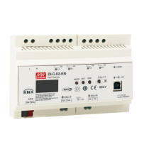
The DLC-02-KN is a KNX to DALI gateway, designed to connect a digital DALI lighting system to a KNX installation. This device facilitates room-based lighting control by integrating it into a higher-level KNX system building management system. It transforms switch and dim commands from the connected KNX system into DALI telegrams and converts status information from the DALI bus into KNX telegrams.

Technical Specifications:

  • Input Voltage: 100 – 305Vac
  • DALI Bus Channels: Two independent DALI Bus channels are supported, with built-in DALI power supply (up to 250mA per bus).
  • DALI ECGs: Connects up to 2 x 64 DALI ECGs.
  • Scenes and Group Settings: Supports a maximum of 16 scenes and group settings per channel.
  • Display and Indicators: Features an LCD display, LED indicators, and buttons for local operation.
  • Relay Outputs: Built-in with 250V/5A x 4 relay.
  • Configuration: Easy installation and configuration via LCD interface and Web browser.
  • Control Effects: Multiple control effects are based on time event and input devices.
  • DALI-2 Devices Support: Supports for DALI-2 devices with Part 202/207/208.
  • DALI Bus Length: The maximum length of ECGs connected is 64 per bus. The maximum length is 300m (with a cable cross-section of 1.5 mm²).
  • KNX Bus Devices: The maximum number of bus devices connected is 256.
  • KNX Bus Line Length: The maximum length of a line segment is 350m, measured along the line between the power supply and the furthest bus device. The maximum distance between two bus devices cannot exceed 700m.
  • KNX Bus Cable Length: The maximum length of a bus line is 1000m, keeping into account all segments.
  • Web Browser End (optional): The maximum length is 100m.
  • Wire Specifications:
    • AC and relay terminals (L,N,K1,K2,K3,K4): Solid wire 0.5 – 4.0mm², Stranded wire 0.5 – 2.5mm², American wire gauge 12 – 26AWG, Wire stripping length 7 – 8mm (0.276” – 0.315”), Screwdriver 3mm Slotted, Recommended tightening torque 5 kgf-cm (4.4 lb-in).
    • DALI terminals (DALI-A, DALI-B): Solid wire 0.5 – 1.45mm², Stranded wire 0.5 – 1.5mm², American wire gauge 16 – 26AWG, Wire stripping length 7 – 8mm (0.276” – 0.315”), Screwdriver 3mm Slotted, Recommended tightening torque 5 kgf-cm (4.4 lb-in).
    • KNX bus terminal (KNX): Solid wire 0.6 – 0.8Ø, Stranded wire ---, American wire gauge 20 – 22AWG, Wire stripping length 5mm (0.196”), Screwdriver ---, Recommended tightening torque ---.

Usage Features:

  • Installation and Mounting: The device can be mounted on a DIN rail (TS35/7.5 or TS35/15). Mounting involves tilting the unit slightly rearwards, fitting the unit over the top hat rail, sliding it downward until it hits the stop, pressing against the bottom for locking, and shaking the unit slightly to check the locking action.
  • Commissioning: The commissioning process involves wiring the DALI segments, connecting the gateway to the KNX bus, connecting all devices with mains, configuring ETS parameters and objects, and finally downloading the ETS application.
  • DALI Commissioning: This involves physical wiring and electronic commissioning of DALI ECGs. The device supports scanning for connected devices and addressing them. ECGs are automatically recognized and assigned a short address from 0-63. The process allows for searching devices, reinstalling, and downloading configurations.
  • Group and Scene Editing: Users can assign ECGs to groups and configure scenes. The device supports up to 16 scenes and allows for editing group commands.
  • Communication Objects: The device supports various communication objects for controlling DALI and KNX functionalities, including:
    • DALI A Broadcast Switch: Used to switch all connected lights simultaneously on or off.
    • DALI A Broadcast Absolute Dimming: Used to simultaneously set all connected lights to a certain value.
    • DALI A Scene Control: Used for calling scenes.
    • DALI A Activate Panic mode: Activates or deactivates the panic mode.
    • DALI A Activate Night Mode: Activates or deactivates the night mode.
    • DALI A Activate Test Mode: Activates or deactivates the test mode.
    • DALI A Power Failure: Reports the presence of DALI bus voltage abnormal.
    • DALI A Short Circuit: Reports the presence of a DALI short-circuit.
    • DALI A ECG Presence: Reports the presence of an ECG disconnect.
    • DALI A ECG Diagnostics: Sends diagnostic values for lamp or ECG errors.
    • DALI A On/Off (Status Group 1-Group16): Sends the on/off status for groups 1-16.
    • DALI B Broadcast Switch, Absolute Dimming, Scene Control, Activate Panic/Night/Test Mode, Power Failure, Short Circuit, ECG Presence, ECG Diagnostics, On/Off (Status Group 1-Group16): Similar functionalities for DALI Bus B.
    • Central Function RTC: Used to set the time and date.
    • A:ECG 1 Relative/Absolute Dimming: Controls relative and absolute dimming for ECG 1.
    • A:ECG 1 On/Off (Status): Sends the on/off status of ECG 1.
    • A:ECG 1 Dimming Value (Status): Sends the dimming value status of ECG 1.
    • A:ECG 1 Lock: Used to lock/unlock the ECG.
    • A:ECG 1 Auto Off: Used to enable/disable the Auto Off function.
    • A:ECG 1 Operation Hours Value (in seconds/hours): Reports the operating hours.
    • A:ECG 1 Operation Hours Exceeded: Reports if operation hours exceed a threshold.
    • A:ECG 1 Alarm Failure (Status): Reports the presence of an ECG disconnect.
    • A:ECG 1 Converter Test Control: Controls a test of a DALI converter.
    • A:ECG 1 Dali Converter Test Result: Sends the result of the last converter test.
    • Group 1 On/Off, Relative/Absolute Dimming, On/Off(Status), Dimming Value(Status), Lock, Auto Off, Operation Hours Value, Operation Hours Exceeded: Similar functionalities for Group 1.
    • Relay 1 On/Off, Lock, On/Off (Status), On/Off (Inverted Status), Forced Control: Controls for Relay 1.
    • Timer 1 Switch, Percentage: Controls for Timer 1.
    • Effect 1 Start/Stop: Activates or deactivates Effect 1.
  • ETS Parameters: The device parameters are distributed across different parameter pages for easy overview and configuration.
    • General Setting: Configures startup timeout, send "operation" cyclic, KNX failure behavior (power down/up), after mode (panic/emergency), broadcast (Dali A/B), and relay control.
    • ECG Settings: Configures ECG name, type (Fluorescent Lamp, Self Contained Battery Lamp, Discharge Lamp, Low Voltage Halogen Lamp, Incandescent Lamp, 0-10V Converter, LED Module, Relay Module), emergency mode value, prolong time on recovery, function test interval, duration test interval, test execution time, DALI power failure behavior, ECG power recovery behavior, dimming curve, switch-on/off values, fade times, status settings, lock object polarity, behavior at locking/unlocking, auto off settings, night mode settings, panic mode settings, and operation hours calculation.
    • Group Settings: Configures group name, DALI power failure behavior, ECG power recovery behavior, dimming curve, switch-on/off values, fade times, status settings, lock object polarity, behavior at locking/unlocking, auto off settings, night mode settings, panic mode settings, and operation hours calculation.
    • Timer Settings: Configures timer function (control type, ECG No., Group No.), timer dimming (hours, minutes, days of the week), addition object, and switch value.
    • Effects Settings: Configures effect repeating and effect function (channel, ECG/Group, value, fade time, delay).

Maintenance Features:

  • Warranty: The product comes with a five-year warranty under normal usage. Mean Well reserves the right to adjust the content of the manual. The latest version of the manual is available on their website.
  • Safety Guidelines:
    • Risk of fatal injury from electrical current: All work must be carried out by skilled electricians.
    • Risk of electrical shock and energy hazard: All failure should be examined by a qualified technician.
    • Installation environment: Do not install the unit in places with high moisture, high ambient temperature, or under direct sunlight.

Meanwell DLC-02-KN Specifications

General IconGeneral
BrandMeanwell
ModelDLC-02-KN
CategoryGateway
LanguageEnglish