72-72T : 28-09-2012
8
6
2.3 Resistance Measurements
1. Connect red test lead to the “VV” jack and black test lead
to the “COM” jack.
2. a) Set Range switch to the V range (72-AUTO)
b) Set Range switch to the V /
/ / (72T-AUTO)
3. Select resistance range by using function button (72T-AUTO).
4. If the resistance being measured is connected to a circuit,
turn off power to the circuit being tested and discharge all
capacitors.
5. Connect test leads across the resistance being measured.
When measuring high resistance, be sure not to contact
adjacent points even if insulated because some insulators
have a relatively low insulation resistance, causing the measured
resistance to be lower than the actual resistance.
6. Read resistance value on digital display. If a high resistance
value is shunted by a large value of capacitance allow display to
stabilize.
2.4 Diode Test
1. Connect the red test lead to the “VV” jack and black test lead
to the “ COM ” jack.
2. a) Set the Range switch to the
/ (72-AUTO)
b) Set Range switch to the V /
/ / (72T-AUTO)
3. Select Diode range by using Function Button.
4. Turn off power to the circuit under test.
5. Touch probes to the diode. A forward-voltage drop is about
0.6V (typical for a silicon diode).
6. If the digital display reads overrange “ OL ”, reverse the lead
connections. The placement of the test leads when the forward
reading is displayed indicates the orientation of the diode. The
red lead is positive and the black lead is negative. If overrange
“ OL ” is displayed with both lead connections, the junction is
open. If a low reading (less than 1000) is obtained with both
lead connections, the junction is shorted internally or (if
junction is measured in a circuit) the junction is shunted by a
resistance less than 1KV. In the letter case the junction must
be disconnected from the circuit in order to verify its operartion.
2.5 Continuity Measurement
1. Connect red test lead to the “VV” jack and black test lead
to the “COM” jack.
2. a) Set Range switch to the
/ (72-AUTO)
b) Set Range switch to the V /
/ / (72T-AUTO)
3. Select Continuity range by using Function Button.
In the continuty test, the beeper sounds cuntinuously, if the
resistance is less than 40V.
2.6 NCV Check (ACV only)
Indicates presence of voltage in an electrical circuit or equipment
without touching them.
1. Set Range switch to the NCV Range.
2. The NCV indicator flashing every 1-2 sec.
3. When the clamp jaw near to the object under test it detected voltage.
The NCV LED is quickly flashing.
l
Detection against inwall outlet is possible.
l
In NCV range meter will be auto power off within 3 minutes,
if no signals is obtained
2.7 Capacitance Measurment (72T-AUTO only)
1. Connect red test lead to the “VV” jack and black test lead
to the “COM” jack.
2. Set Range switch to the V /
/ /
3. Select “ ” Range by using function button.
4. Turn off power to the circuit under test.
the “REL” annunciator is displayed and the respective range is active
only. This function is available for DCV, ACV, Current, Resistance &
Capacitance. In Capacitance “REL” acts as a “REL zero”.
NOTE : Use “REL” button to enter the relative mode, the “REL”
annunciator turn on, zero the display and store the displayed reading as
a referance value.
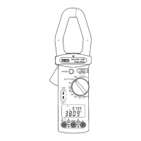
2.1 Current Measurements
1. Set the Range switch to the “A” range.
2. Press the trigger to open transformer jaws, clamp onto one
conductor only and release trigger. Jaws should be completely
closed. Read the current directly on the display. It is
recommended that the conductor be placed at th e center of
the closed jaws for maximum accuracy (Fig. - 1).
2.2 Voltage Measurements (AC or DC)
1. Connect the red test lead to the “VV” jack and the black test lead
to the “COM” jack.
2. Set the Range switch to the desired Voltage type (AC or DC)
3. Connect the test leads to the device or circuit being measured.
4. For DC, a (-) sign is displayed for negative polarity; positive
polarity is implied.
Fig. 1
73
5. By using “REL” button get zero display.
6. Connect the test leads to the capacitor and read the capacitance
directly from the display.
2.8 Frequency Measurment
1. Connect red test lead to the “VV” jack and black test lead
to the “COM” jack.
2. Set Range switch to the Hz
3. Connect the test leads to the points of measurment and read the
frequency from the display.
2.9 Temperature Measurment (72T-AUTO only)
1. Set range switch to
0
C possition.
2. Connect the thermocouple “+, -” at VV and COM input terminals.
3. Touch the end of temperature probe to the area or surface of the
object whose temperature is to be measured.
Important : To avoid heat damage to the meter keep it away from
sources of very high temperature. The life of the temperature probe is
also reduced. When subjected to very high temperature.
5
 Loading...