3510PHW : 28-09-2012
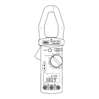
HVAC TRMS CLAMP METER
MODEL : 3510PHW
2
3 4
1
®
INSTRUCTION MANUAL
2. TECHNICAL SPECIFICATIONS
2.1 Environment Conditions :
1. Installation category III
2. Pollution degree 2
3. Altitude up to 2000 meters
4. Indoor use only
5. Relatively humidity 80% max.
6. Operation ambient 0 ~ 50
0
C
2.2 Maintenance :
1. Repairs or servicing is not covered in this manual, should
only be performed by qualified personnel.
2. Periodically wipe the case with a dry cloth. Do not use
abrasives or solvents on this instrument.
2.3 Features :
2.3-1 HVAC and Electrical :
1. To check current drawn by motors and compressors.
2. To use MAX/MIN/Recording in the temperature mode
to assess the efficiency.
3. To test run / start capacitors.
4. To measure low voltage control signals.
5. To measure flame protection diode current (<200mA)
in a heater control.
6. To analyze temperature and power data with the aid
of the time stamp.
7. To measure high resistance.
8. To capture max. load current.
9. To determine peak power demand periods.
10. To monitor motors and other loads for excess heat.
1. SAFETY INFORMATION
l
Read the following safety information carefully before
attempting to operate or service the meter.
l
To avoid damages to the instrument do not exceed the
maximum limits of the input values shown in the technical
specification tables.
l
Do not use the meter or test leads if they look damaged.
l
Use extreme caution when working around bare conductors
or bus bars. Accidental contact with the conductor could
result in electric shock.
l
Use the meter only as specified in this manual; otherwise,
the protection provided by the meter may be impaired.
l
Read the operating instructions before use and follow all
safety information.
l
Caution when working with voltages above 60VDC or
30VAC RMS. Such voltages cause a shock hazard.
l
Before taking resistance measurements or testing acoustic
continuity, disconnect circuit from main power supply and
all loads from circuit.
Safety symbols
Caution refer to this manual before using the meter.
Dangerous voltages.
Meter is protected throughout by double insulation
or reinforced insulation.
When servicing, use only specified replacement
parts.
Complies with EN-61010-1, IEC 1010-2-32
2.3-2 Functions :
1. True RMS, ACV, ACA, KW, KVA.
2. 9999 counts dual display LCD with unit sign.
3. Dual KW + hp, KW +P.F, KW+KVAR, KVA + u, A + V
(5 types)
4. Temp.
0
C/
0
F
5. Dual display A + Hz, V + Hz.
6. Data hold mode/MAX-MIN mode
7. Auto Power Off and to disable Auto Power off
function.
2-4 General Specifications :
Maximum voltage between any terminal and earth ground :
600V rms.
Numerical dual display : Dual display 4 digit LCD
maximum reading 9999.
(10,000 Count Reading)
Battery life : approx. 32hr
Low battery indication : The “
” is displayed when
the battery voltage drops below
the operating voltage.
Auto power off time : approx. 30 minutes. (To disable
Auto Power Off, please refer to
4-9)
Sampling rate : 2.5 times / sec (Digital display)
1 times / 6 sec (on KW,KVA)
Jaw opening diameter : Cables F 43mm
Operating temperature : 0
0
C to 50
0
C (32
0
F to 122
0
F)
and humidity R.H. < 80% non-condensing.
Temperature coefficient : 0.1 x (specified accuracy) /
0
C
(< 18
0
C or > 28
0
C, < 64
0
F or >
82
0
F)
Storage temperature : - 10
0
C to 60
0
C (14
0
F to 140
0
F)
and humidity R.H. < 70% non-condensing.