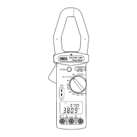
3510PHW : 28-09-2012
14
15 16
13
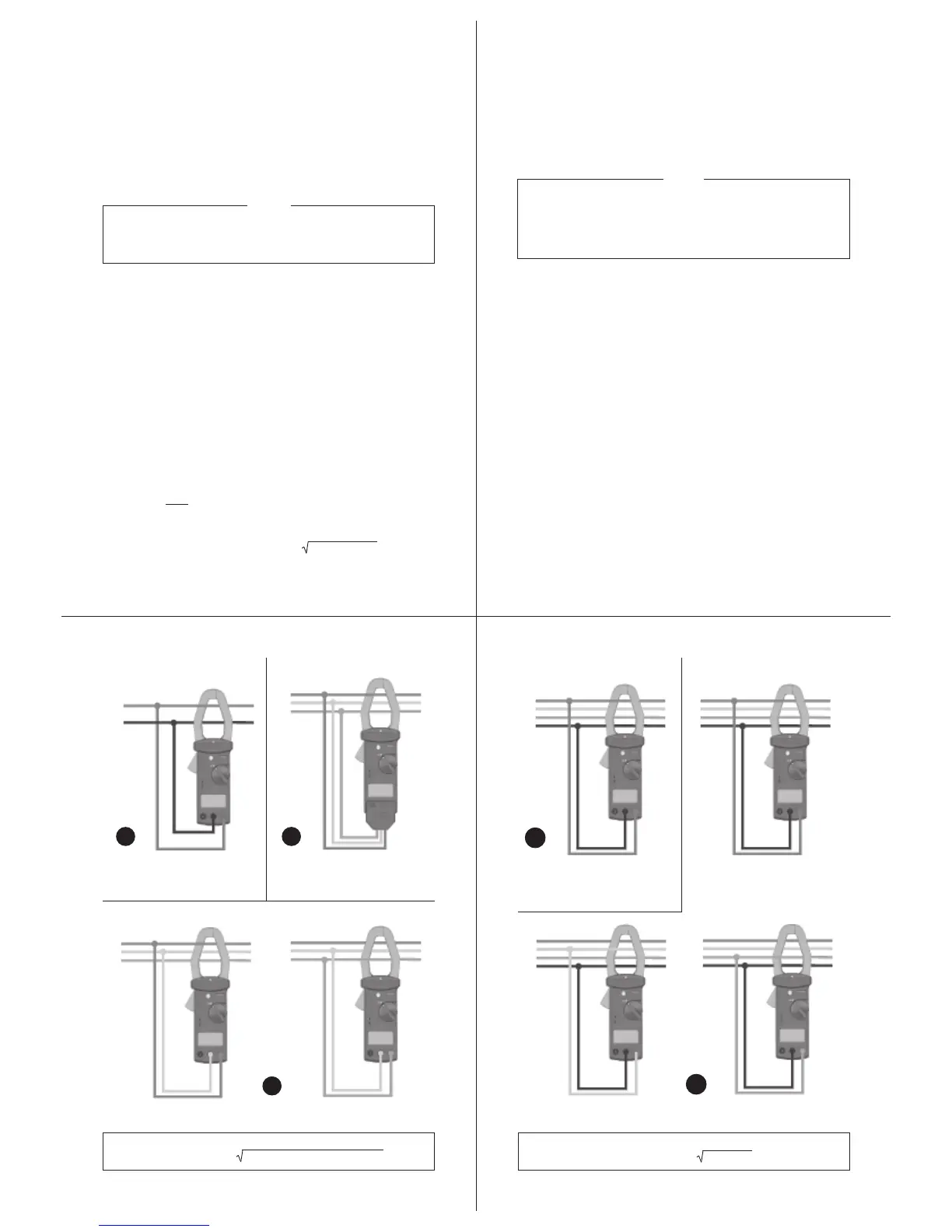
8. For 3 Phase 3 Wire balanced load system, insert 3f
plug in adapter in terminals “ COM ” and “ V ”. Connect
three crocodile clips to appropriate phase (R, Y and B).
Clamp “ R ” Phase conductor. 3f
power = 3 x Meter
indication (Refer fig 3).
9. For measurement in other systems please refer figures
4, 5 and 6.
NOTE
1. The “ + ” sign printed on panel must face the power
source for correct measurement.
2. If the device under test is switching mode power, the
meter KW, PF and
u
reading may be incorrect.
R
Y
B
N
Load
R
Y
B
N
Load
R
Y
B
N
Load
R
Y
B
N
Load
3f 4W Balanced System
Measured Value
= KW1, HP1, KVAR1 & KVA1
3f Values
= 3 x Displayed Value for
KW, HP, KVAR & KVA
Fig.
5
Fig.
6
Measured Value
= KW3, HP3, KVAR3 & KVA3
Measured Value
= KW2, HP2, KVAR2 & KVA2
3
f
Values = (KW1+KW2+KW3) or (HP1+HP2+HP3) or (KVAR1+KVAR2+KVAR3)
or (KVA1+KVA2+KVA3) 3
f
PF = KW
T
/
KW
T
+ KVAR
T
or KW
T
/
KVA
T
2
2
4.2 AC Current Measurement
1. Set the rotary switch to the “ A ” position.
2. Press the trigger to open the jaw and fully enclose the
conductor to be measured. No gap is allowed between
the two half jaws.
3. The clamp will automatically select the appropriate range.
4. Read the current and frequency values displayed on
the LCD.
NOTE
The sensitivity for Current frequency measurement is
6A and the frequency range is 40 ~ 400Hz. If the
frequency is less than 40Hz the LCD may show Hz.
R
N
Load
R
Y
B
Load
3f
Adapter
1f 2W System
3f 3W Balanced System
KW, HP, PF, f, KVAR, KVA
3f Values
= 3 x Displayed Value for
KW, HP, KVAR & KVA
Fig.
2
Fig.
3
R
Y
B
Load
R
Y
B
Load
Measured Value
= KW1, HP1 & KVAR1
3f Values = (KW1+KW2) or (HP1+HP2) or (KVAR1+KVAR2)
3f PF = Cos[tan
-1
3(KW1-KW2) / (KW1+KW2)]
Fig.
4
Measured Value
= KW2, HP2 & KVAR2
3f 3W Unbalanced System
3f4W Unbalanced System
4.3 AC Power KW, KVA, PF (Power Factor) and
u u
u u
u
(Phase
Angle) Measurement
1. Set the rotary switch to the “ KW/KVA ” position (refer to
figure 2).
2. Insert the test leads in to the input jack. (Black to COM
and Red to V)
3. Connect the Black lead COM to the neutral line.
4. Connect the Red lead V to the power line and clamp
the same conductor where V (red) terminal is connected.
5. The power clamp will automatically select the appropriate
range.
6. Read the watt and hp values displayed on the LCD.
7. Press range button to display required parameters.
PF =
KW
= COS
u
(
u
= Phase Angle)
KVA
KVA (Apparent Power) : KVA = (V*A)/1000
KVAR (Reactive Power) : KVAR = (KV-A)
2
-(KW)
2
=KVA*sin
u
HP (Horse Power) = 746W
 Loading...