Do you have a question about the MEDC XB15 and is the answer not in the manual?
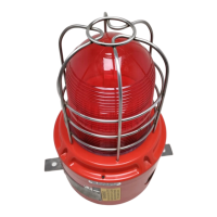
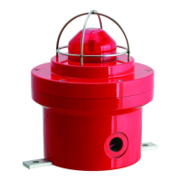
The device described in this manual is the MEDC XB15 Xenon Beacon, a visual alarm device designed for use in potentially explosive atmospheres and harsh environmental conditions. It is constructed with a glass reinforced polyester enclosure, offering excellent corrosion resistance. The stainless steel screws and mounting bracket are also corrosion-free.
The XB15 Xenon Beacon serves as a visual warning device, emitting a bright xenon flash to alert personnel in hazardous environments. It is designed to operate on a supply voltage tolerance of +/- 20%. The AC versions of the beacon are designed to operate at a supply voltage tolerance of +/- 10%. The telephone initiate versions of the Beacon are not included in this safety manual. Under normal (fault) operating conditions, the XB15 Beacon will provide a spherical visual warning light when required by the system. Under fault conditions, the failure mode of the Beacon is a spherical visual warning light.
The XB15 Xenon Beacon is certified for use in a safety system conforming to the requirements of IEC61508. The device has a Safety Integrity Level (SIL) rating, with a Hardware Fault Tolerance (HFT) of 0. The Probability of Dangerous Failure (PFDavg) is 2.18E-03 for SIL 2 and 5.85E-06 for SIL 1, depending on the specific application and configuration. The device's safety function is to provide a cyclical visual warning light when energized.
The beacon is available in various temperature classes (T4, T5, T6) depending on the energy tube and ambient temperature. For example, with a 1.5J & 10J energy tube, the T-rating is T4 for Tamb up to +70°C, T5 for Tamb up to +55°C, and T6 for Tamb up to +40°C. With a 5J energy tube, the T-rating is T5 for Tamb up to +55°C and T6 for Tamb up to +40°C. The device is certified to IEC60079-0, IEC60079-1, and IEC60079-31 for hazardous areas. It carries ATEX certification with an II 2 GD marking, indicating suitability for use in Zone 1 (gases) and Zone 21 (dusts) industrial environments. The rating is 21.6V-26.4V DC Absolute, with 0.99 Amps. It has an Environment Type B for outdoor applications and an IP Code (IP33C) to BS EN 60529:1992. The device complies with relevant European directives, including 89/106/EEC.
The XB15 Xenon Beacon can be either directly mounted using the inserts molded into the back of the enclosure (standard) or an optional backstrap can be fixed to the base of the device, giving an optional mounting position for when direct mounting is deemed unfeasible. For EN54 23:2010 Compliance, the mounting back strap must be positioned in the horizontal plane. If the direct mount option is ordered, the mounting holes must also be on the same horizontal plane as the back strap. The 2 off inserts in the base of the enclosure are designed to accept an M5 screw or bolt. The length of screw required is Thickness of mounting surface + 10mm. The 2 off Ø8.5mm mounting holes in the optional backstrap are designed to accept an M8 screw or bolt.
The beacon can be mounted on ceilings or walls. For ceiling mounted devices (C-x-y), the maximum height is 3, 6, or 9m, and the diameter in meters of the cylindrical volume covered (to a minimum level of 0.4 lux) when the device is mounted to the ceiling at a height of 3, 6, or 9m. For example, C-3-32 corresponds to a ceiling mounted device giving a coverage cylindrical volume of 32m, when mounted at 3m. The projected space sits within the cylindrical volume and ensures that all areas meet the required illumination of 0.4 lux. The tip to convert the coverage diameter y to the width of a square room is y/1.414m. For wall mounted devices (W-x-y), the maximum height is 2.4m, and the width in meters of the square volume covered (to a minimum level of 0.4 lux) when the device is mounted at a height x. For example, W-8-13 corresponds to a wall mounted device giving a coverage cuboid volume of 8m x 13m x 13m, when mounted at a height of 8m. If the area to be covered is not square, use the larger of either the length or width to ensure that the whole area is covered.
During the working life of the unit, it should require little or no maintenance. GRP will resist attack by most acids, alkalis and chemicals and is as resistant to concentrated acids and alkalis as most metal products. However, if abnormal or unusual environmental conditions occur due to plant damage or accident, then visual inspection is recommended. If the unit requires cleaning, then only clean exterior with a damp cloth to avoid electro-static charge build up. Replacement of the xenon tube (see below) can be carried out by competent site personnel. Other repairs should be undertaken by returning the unit to MEDC. If a unit fault should occur, then the unit can be repaired by MEDC. All parts of the unit are replaceable. If you acquired a significant quantity of units, then it is recommended that spares are also made available. Please discuss your requirements with the technical sales engineers at MEDC.
Unscrew the grub screw (2.0mm A/F hexagon key) in the flange of the cover 3 full turns (Do not fully unscrew). Unscrew and remove the cover and lens assembly using the spanner supplied to gain access to the inside of the unit. Unscrew the 2 off thumbscrews and carefully lift the PCB assembly clear of the mounting pillars to gain access to the terminals. Once termination is complete, replace the PCB assembly onto the mounting pillars and fully tighten the thumbscrews, taking care not to overtighten them. Replace the cover assembly, ensuring the cover is fully screwed down. There should be a maximum gap of 0.2mm between the faces of the cover and enclosure to ensure o-ring compression. Ensure the cover seal is correctly seated in its groove during re-assembly. Re-tighten the grub screw (2.0mm A/F hexagon key) in the cover flange to secure the cover.
The wiring diagram shows connections for +VE IN, +VE OUT, -VE IN, -VE OUT, and NOT USED terminals, along with an optional EOL resistor (R1). The terminals are numbered 1 through 12.
The following conditions apply to the installation, operation and maintenance of the assessed equipment. Failure to observe these may compromise the safety integrity of the assessed equipment:
| Brand | MEDC |
|---|---|
| Model | XB15 |
| Category | Security System |
| Language | English |