29
Uninterruptible power supply MEg102
are galvanically isolated by transformers, they are to be connected to the power supply
unit using screw-on terminals. ere is a button on the outside of the plastic cover to stop
the battery operation.
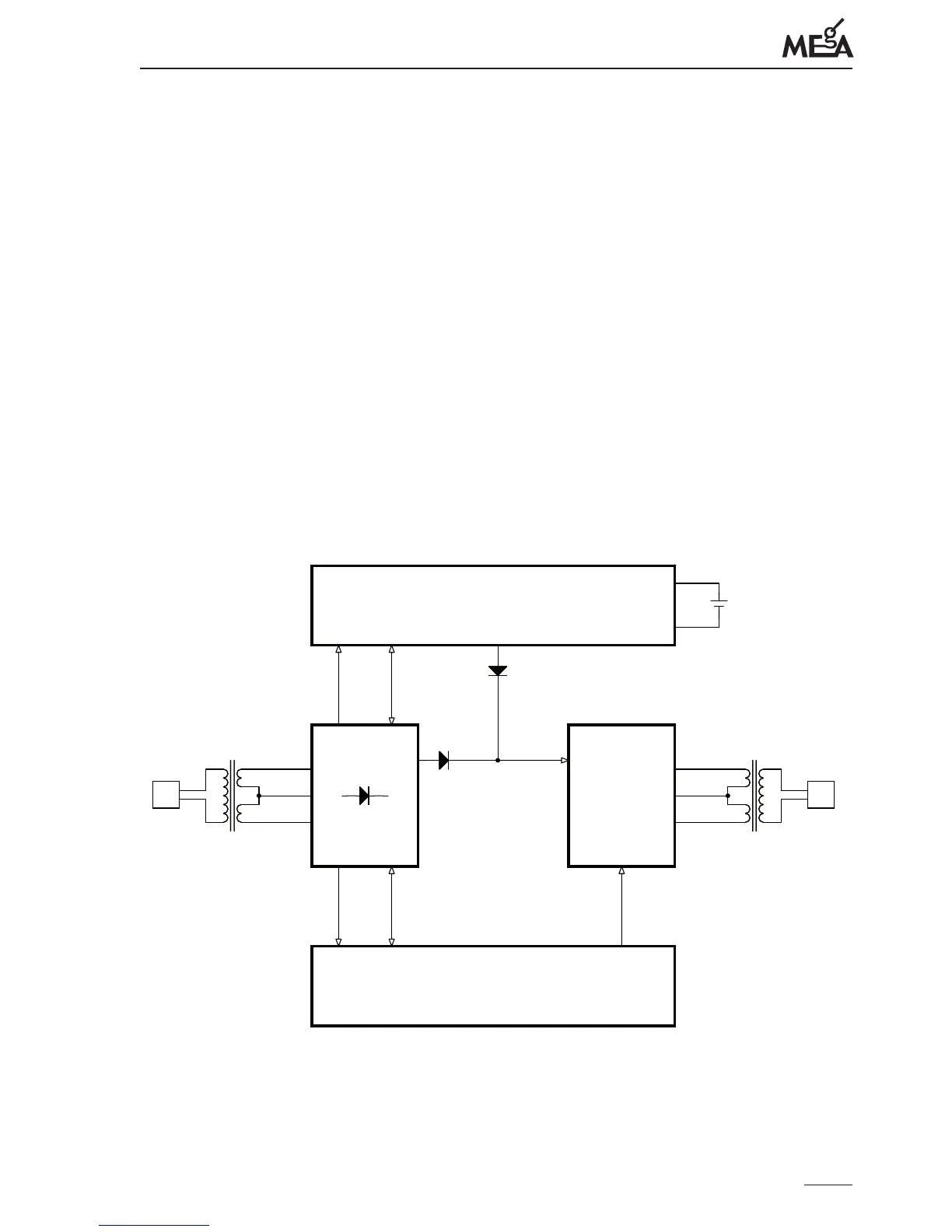
e principle of the uninterruptible power supply MEg102 is represented by the group
diagram in Fig. 1. e input voltage U
inp
applied to the terminals IN is converted by
the transformer T1 and the subsequent rectier to the DC voltage, which is converted
by means of a synchronized generator and output switches to the AC pulse voltage and
transformed to U
outp
by the transformer T2 to power supply the instrument. e voltage
U
outp
is on the terminals of the power supply unit MEg102.
e U
inp
voltage drop below the lower limit indicates with the SitOK signal to the control
circuits of the accumulator to change over the battery supply. e battery operation is
nished when U
inp
returns above the lower limit plus necessary hysteresis or when the
period set by the internal generator expires (default 180 sec) or when the external button
Battery stop is pressed for about 2 seconds.
Fig. 1: Group wiring diagram of uninterruptible power supply MEg102.
Battery control
Output
switches
SitOK Upom
UpomSync
Control signal generator
Uinp Uoutp
T1T1
+
Bat
+
Battery
T2T2
 Loading...