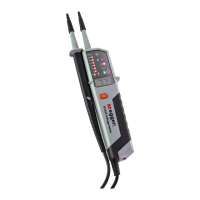
The Megger TPT420 is a two-pole voltage tester designed for electricians and electrical engineers, offering a comprehensive suite of functions for voltage indication, continuity, and phase rotation. It features both LCD and LED displays for clear readings and an acoustic sounder for audible indications.
Function Description
The primary function of the TPT420 is AC and DC voltage measurement, ranging from 12 V to 1000 V AC and 1500 V DC. It also includes a continuity function, measuring from 0 to 500 kΩ. A key safety feature is its ability to indicate dangerous test voltages even when the batteries are exhausted. The device is designed not to trip RCDs, RCBOs, or Safety Breakers when conducting phase-to-earth tests. The phase rotation indication function is simplified, avoiding the need to cross test probes. Additionally, a bright LED torch is integrated for safe operation in poorly lit environments.
Important Technical Specifications
- Voltage Range: 12 V to 1000 V AC and 1500 V DC (40-400 Hz, DC±).
- LED Nominal Voltage: 12 V, 24 V, 50 V, 120 V, 230 V, 400 V, 690 V, 1000 V AC/DC (40-400 Hz, DC±), according to EN61243-3.
- Voltage Warning Indication LED: <50 V AC, <120 V DC.
- Response Time: <1s at 100% of each nominal voltage.
- LCD Range: 12 V to 1000 V AC and 1500 V DC (40-400 Hz, DC±).
- LCD Resolution: 0.1 V.
- LCD Accuracy: ±3% ±5dgt.
- LCD Over Range Indication: "OL".
- Peak Current: Is < 3.5 mA (at 1000 V).
- Measurement Duty: 30 s ON (operation time), 240 s OFF (recovery time).
- Internal Battery Consumption: Approx. 80 mA.
- Single-Pole Phase Test Voltage Range: 100 V to 1000 V AC (50/60 Hz).
- Phase Rotation Test: 120 V to 400 V earth-to-phase, AC 50/60 Hz.
- Continuity Test: 0 to 500 kΩ ± 50%.
- Battery: 2 x 1.5 V AAA, IEC R03.
- Temperature: -5 °C to 40 °C operation; -20 °C to 70 °C storage, no condensation.
- Humidity: Max 85% RH.
- Altitude: Up to 2000 m.
- Over Voltage Category: CAT IV / 1000 V.
- Safety Standard: EN61243-3.
- Pollution Degree: 2.
- Protection: IP64.
- Dimensions: 67 (W) x 205 (L) x 19 mm (D).
- Weight: 180 g.
- Insulation: Continuous double or reinforced insulation, complying with category II DIN EN 61140.
- Compliance: EMV Directive (2014/30/EU), Low Voltage Directive (2014/35/EU), and EN 61326-1, EN61243-3 standards.
Usage Features
- Auto-Power-On/Switching On: The tester automatically switches on when it detects continuity, an AC or DC voltage above approximately 10 V, or a live phase on L2 (single-pole test). It can also be manually switched on using the torch light button.
- Auto-Power Off: The device automatically powers off after 5 seconds if no signal is detected by the probes. The torch light switches off after approximately 10 seconds.
- Self-Test: Before any measurements, a self-test should be performed by shorting the probe tips. The continuity LED will illuminate, and a continuous audible tone will be heard, confirming sufficient battery power. If only the voltage warning LED illuminates and the LCD is blank, the batteries should be checked.
- Continuity Test: For continuity testing, ensure the circuit is not energized. Connect both test probes to the circuit. The continuity LED will illuminate, and the buzzer will sound continuously for continuity less than 500 kΩ. Note that continuity measurement is not displayed on the LCD.
- Diode Test: Connect the L1- probe to the anode and the L2+ probe to the cathode of the diode. The continuity LED will illuminate, and the buzzer will sound. Reversing the connections will result in no illumination or sound.
- AC/DC Voltage Test: Connect both probes to the circuit under test. Voltage is indicated by both LEDs and the LCD display. The buzzer sounds when a threshold voltage of approximately 38 V AC or 100 V DC is exceeded.
- Voltage Polarity Indication:
- AC: Both + and - 12 V LEDs are on.
- +DC: +12 V LED is on.
- -DC: -12 V LED is on.
- When the L2 probe is positive (negative), the polarity indication LED indicates "+DC" ("-DC").
- For voltages over 1000 V AC and 1500 V DC, the LCD will display 'OL'.
- Single-Pole Phase Test: Hold the tester securely and connect the "L2 +" probe to the object under test. The voltage warning LED lights up, and the buzzer sounds when a voltage of approximately 100 V AC or more is present. This test's effectiveness may be affected by insulation or grounding conditions. It should not be the sole method for verifying live circuits.
- Phase Rotation Test: Hold the tester and remote probe firmly, ensuring hands are behind the barriers. Connect the probes to the phases to be tested. Phase-to-phase voltage is indicated by voltage LEDs and the LCD.
- R LED lights up for Right rotary field (L1, L2, L3).
- L LED lights up for Left rotary field (L1, L3, L2).
- This test detects the phase rising order referencing the user as earth. Its function may be affected by insulation or grounding conditions.
- Torch Light: Pressing the torch light button turns on the light, which automatically turns off after approximately 10 seconds.
- Safety Barriers: Hands should be kept behind the barriers on the main body and remote probe during testing to avoid touching the tips.
- GS38 Shrouds: The device comes with GS38 shrouds as standard. To comply with GS38 (minimum exposed tip), the metal caps on each prod must be unscrewed and replaced with the supplied plastic tip shrouds.
Maintenance Features
- Battery Replacement: Batteries are exhausted when the "continuity/self" test fails. A battery symbol on the LCD indicates low battery. To replace, remove the probes from any testing point, unscrew the battery cap (e.g., with a screwdriver), pull out the cap, replace with new AAA / IEC R03 1.5 V batteries according to the engraving, and re-assemble, ensuring the cap is properly locked.
- General Condition: The instrument must be in good working order, clean, and dry, with no broken or damaged leads, probes, or case. Do not use if any functions are not working correctly.
- Storage: Remove batteries if the tester is not to be used for a long period. Do not use with exhausted or leaked batteries.
- Repair and Warranty: The instrument contains static-sensitive devices. If its protection is impaired (e.g., visible damage, failure to perform measurements, prolonged storage under unfavorable conditions, or severe transport stresses), it should be sent for repair by suitably trained and qualified personnel. Unauthorized repair or adjustment will invalidate the warranty.
- Returning for Repair: A Returns Authorisation number must be obtained by contacting Megger before returning an instrument for repair. This number should be clearly marked on the packaging. The instrument should be sent freight paid. For repairs outside the warranty period, an estimate will be provided if required.
- WEEE Directive: The crossed-out wheeled bin symbol indicates that the instrument and batteries should not be disposed of with general waste. Megger is registered in the UK as a Producer of Electrical and Electronic equipment (registration no: WEE/DJ2235XR). Users in the UK can contact B2B Compliance for disposal. Users in other EU parts should contact their local Megger company or distributor.
- Battery Disposal: Batteries are classified as Portable Batteries under the Batteries Directive. Contact Megger Ltd for safe disposal instructions. Megger is registered in the UK as a producer of batteries (registration number: BPRN01235). Further information is available on www.megger.com.