3
AC equivalent circuit
inside the main module
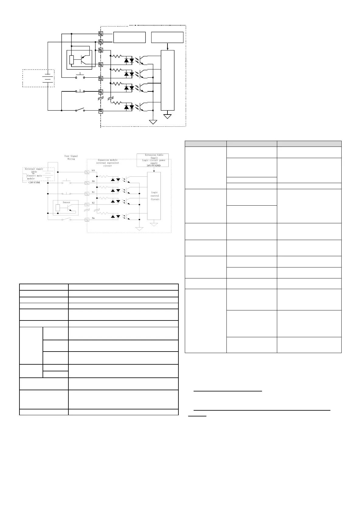
The I/O extension module internal equivalent sources and the input
signal wiring are shown below.
7.2 output characteristics and signal specifications
Output port specifications
LED is on when optical coupler is driven
Leakage current of
open circuit
Y0~Y7:0.3A/1 point;Others:0.3A/1 point;0.8A/4
point;1.2A/6 point;1.6A/8 point
Y0~Y7:0.9W/24Vdc
Others:1.5W/24Vdc
Y0~Y7:Less than 5 us(
Load current above 10 mA
)
Others:Less than 0.5ms(
Load current above 100 mA
)
Y0~Y3:Each channel:200kHz;Y4~Y7:Each
channel:100kHz
Y0,Y1,COM0;Y2,Y3,COM1;Y4,Y5,COM2;
Y6,Y7,COM3;
Y10~Y13,COM4;Y14~Y17,COM5
8. Power operation and routine maintenance
8.1 Power operation
After the connection, item by item, check to ensure that no foreign
connections fall into the cabinet inside,heat flow
1.Switch on the POWER of the controller, POWER light should be light;
2.Start the PC software programming, Download the user program
will be programmed into the controller;
3.Download program calibration finished.
8.2 Routine Maintenance
Routine maintenance checking should pay attention to the following:
1.Ensure working environment clean and tidy, controller, avoid foreign
body in dust into machine;User equipment
2.To maintain good ventilation controller;
3.All wiring connections and terminals, fixed tightly in good condition
4. Observe the indicator light controller, observe LCD display screen
and state information.
9. The common problems and solutions
When the controller can not work normally, please check in turn:
1. Power line connection and protection of electrical switches and
related conditions, ensure controller has been reliable power supply;
2. The connection of user terminals is strong;
3. Refer to the fault record. If the above checks are done and when
confirmed controller still unable to work, Can refer to the table and
working status of the controller for analysis
Power lights and other
lights are not bright
Power supply pressure loss
or voltage is too low
Check the power supply condition,
be ruled out
Disconnect the power
switch or fuse blown
Check the switch, wires or fuse
condition, be ruled out
Power lines contact
undesirable
Check and make sure:1.24VL、24
VN terminal voltage whether
between the normal range; 2.
P24V and COM between
terminals whether short circuit or
load is too large
P24V/COM auxiliary
power output is circuit,
leading to the current limit
RUN indicator and
ALARM indicater are
not bright
Confirm the power under normal
operation of the menu in controller
test
LCD can't display
properly
Power wiring undesirable,
or P24V/COM a short
circuit
Confirm the power under normal
operation of the menu in controller
test
External connection is bad
Re-wiring,make sure the eiring is
correct.
Frequency movement of relay port
can be swapped with the port idle.
Can't download,
upload, monitoring
Programme cable connect
bad
Use the special programming
cable of Megmeet controller
A serial port can't
control the other
equipment
Cable connection bad, or
connection error, such as
the signal attribute TXD
and RXD confusion
Will signal lines connected
correctly
Communication master
and slave feature is
inconsistent,such as baud
rate,parity,data
bits,address.
The communation parameter is set
to the same.
Communication protocol is
inconsistent with the
master and slave
Set the same communation
protocal.
Notice
1. The warranty range is confined to the PLC only.
2. Warranty period is 18 months, within which period Megmeet
Network Power conducts free maintenance and repairing to the PLC
that has any fault or damage under the normal operation conditions.
3. The start time of warranty period is the delivery date of the
product, of which the product SN is the sole basis of judgment. PLC
without a product SN shall be regarded as out of warranty.
4. Even within 18 months, maintenance will also be charged in the
following situations:
Damages incurred to the PLC due to mis-operations, which are
not in compliance with the User Manual;
Damages incurred to the PLC due to fire, flood, abnormal voltage,
etc;
Damages incurred to the PLC due to the improper use of PLC
functions.
5. The service fee will be charged according to the actual costs. If there
is any contract, the contract prevails.
 Loading...