1
MC100-2TC/4TC Thermocouple
Module User Manual
Note:
To reduce the chance of accident, please carefully read the operating
instructions and safety precautions prior to use. Only adequately trained
personnel shall install or operate this product. In operation, strict compliance
with applicable safety rules in the industry, the operating instructions and
safety precautions in this book is required.
This manual MC100 series for the following members:
MC100-2TC Thermocouple Module
MC100-4TC Thermocouple Module
Version 1.0
Revision date January 15, 2010
BOM R29090040
1 Port Description
1.1 Port
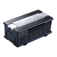
The extension port and user port of MC100-2TC/4TC are both protected by a
cover, as shown in Figure 1-1. Removing the covers reveals the extension
port and user port, as shown in Figure 1-2.
Figure 1-1 MC100-2TC/4TC appearance
Figure 1-2 MC100-2TC/4TC ports
The extension cable connects MC100-2TC/4TC to the system, while the
extension port connects MC100-2TC/4TC to another extension module of the
system. For details on connection, see 1.2 Connecting Into System.
The user port of MC100-2TC/4TC is described in Table 1-1.
Table 1-1 User port description
Positive poles of thermalcouples for
channels 1 to 4
Negative poles of thermalcouples for
channels 1 to 4
6, 8, 10, 12,
14, 16, 18, 20
1.2 Connecting Into System
Through the extension cable, you can connect MC100-2TC/4TC to MC100
series basic module or other extension modules. See Figure 1-3.
Basic module
Extension module
Removing extension port cover
before connection
Extension cable
Figure 1-3 Connecting into system
1.3 Wiring
The wiring of user port is shown in Figure 1-4.
Figure 1-4 Wiring of MC100-2TC/4TC user port
The circled 1 ~ 6 stands for the six points to be observed during wiring:
1. Thermocouple signals are connected through screen compensation cables,
which should be routed separate from power cables or other EMI-generating
cables. Long compensation cables are susceptible to EMI, so the
compensation cables should be advisably shorter than 100m. Compensation
cable has impedance, which can cause measurement error. This problem
can be addressed through characteristics adjustment. For details, see 3
Setting Characteristics.
2. If strong EMI exists, connect the FG and PG terminals together.
3. Properly ground the module’s PG terminal.
4. The basic module’s 24Vdc auxiliary power or any qualified external power
supply can be used to feed the module’s analog circuit.
5. Short the positive and negative terminals of unused channels to avoid
detecting error data from that channel.
2 Indices
2.1 Power Supply
Table 2-1 Power supply
24Vdc (-15%~20%), maximum allowable ripple voltage: 5%,
50mA (from the basic module or external power supply)
5Vdc, 72mA (from basic module)
2.2 Performance
Table 2-2 Performance
Thermocouple: type K, J, E, N, T, R or S (all accessible
to each channel), 4 channels
(240ms±2%)ms × 4 channels (no conversion for unused
channels)