3
as per the following formula before using them in the characteristic setting:
Celsius = 5/9 × (Fahrenheit - 32)
9. BFM#4094: software version information, displayed automatically as
Module Version in MC100-2TC/4TC Configuration dialogue box of the host
software, as shown in Figure 4-1.
10. BFM#4095: module ID. The ID of MC100-2TC/4TC is 0x4041. The PLC
user program can use this code to identify the module before transceiving
data.
3 Characteristic Setting
The input channel characteristic of MC100-2TC/4TC is the linear relationship
between the channel’s analog input A and digital output D. It can be set by
the user. Each channel can be considered as the model shown in Figure 3-1.
As it is of linear characteristic, the channel characteristic can be defined by
just two points: P0 (A0, D0) and P1 (A1, D1), where D0 is the channel’s
digital output corresponding to analog input A0, and D1 is the channel’s
digital output corresponding to analog input A1.
Channel
D
Digital output
A
Analog input
Channel model
D1
A(0.1℃)
Channel characteristic setting
D0
A0 A1
P 1
P0
D(0.1℃)
Figure 3-1 MC100-2TC/4TC channel characteristic setting
The channel characteristic setting is used to correct the onsite linear error in
MC100-2TC/4TC measurement caused by the different ambient
temperatures and compensation cables.
To simplify the operation process without affecting functions, A0 and A1 are
respectively fixed to 0 and 12,000 (unit: 0.1°C) in the present mode. That is to
say, the A0 and A1 in Figure 3-1 are respectively 0 and 12,000 (unit: 0.1°C).
Users cannot change their values.
If you just set the channel mode without changing D0 and D1, the channel
characteristic vs. 0 mode should be as shown in Figure 3-2.
12000
12000
- 1000
0
Default (not adjusted)
- 1000
A (0.1
D(0.1
°
C
)
°
C
)
Figure 3-2 Characteristic vs. 0 mode without changing D0 and D1
Note that when the mode is set to 1 or 3, the output will be in 0.1°F unit, and
the temperature data read from the output data zone will be in 0.1°F unit. But
the data in the channel characteristic setting zone will still be in 0.1°C unit,
which means the data in the channel characteristic setting zone is always in
0.1°C unit. Keep this in mind when changing D0 and D1.
You can change the characteristics by changing D0 and D1. The setting
range of D0 is -1000~1000 (0.1°C); D1, 11000~13000 (0.1°C). If the setting is
outside this range, MC100-2TC/4TC will not accept it, but maintain the
original valid setting. Figure 3-3 provides you an example of changing K type
and J type thermocouple characteristic when the MC100-2TC/4TC measured
value is 5°C (41°F) higher the actual value.
12000
-
1000
0
- 950
A ( 0.1 )
D ( 0.1 ° )
P0
P1
- 50
11950
D 0 = - 50
D 1 = 11950
C
°
C
Figure 3-3 Changing characteristic
4 Application Example
4.1 Basic Application
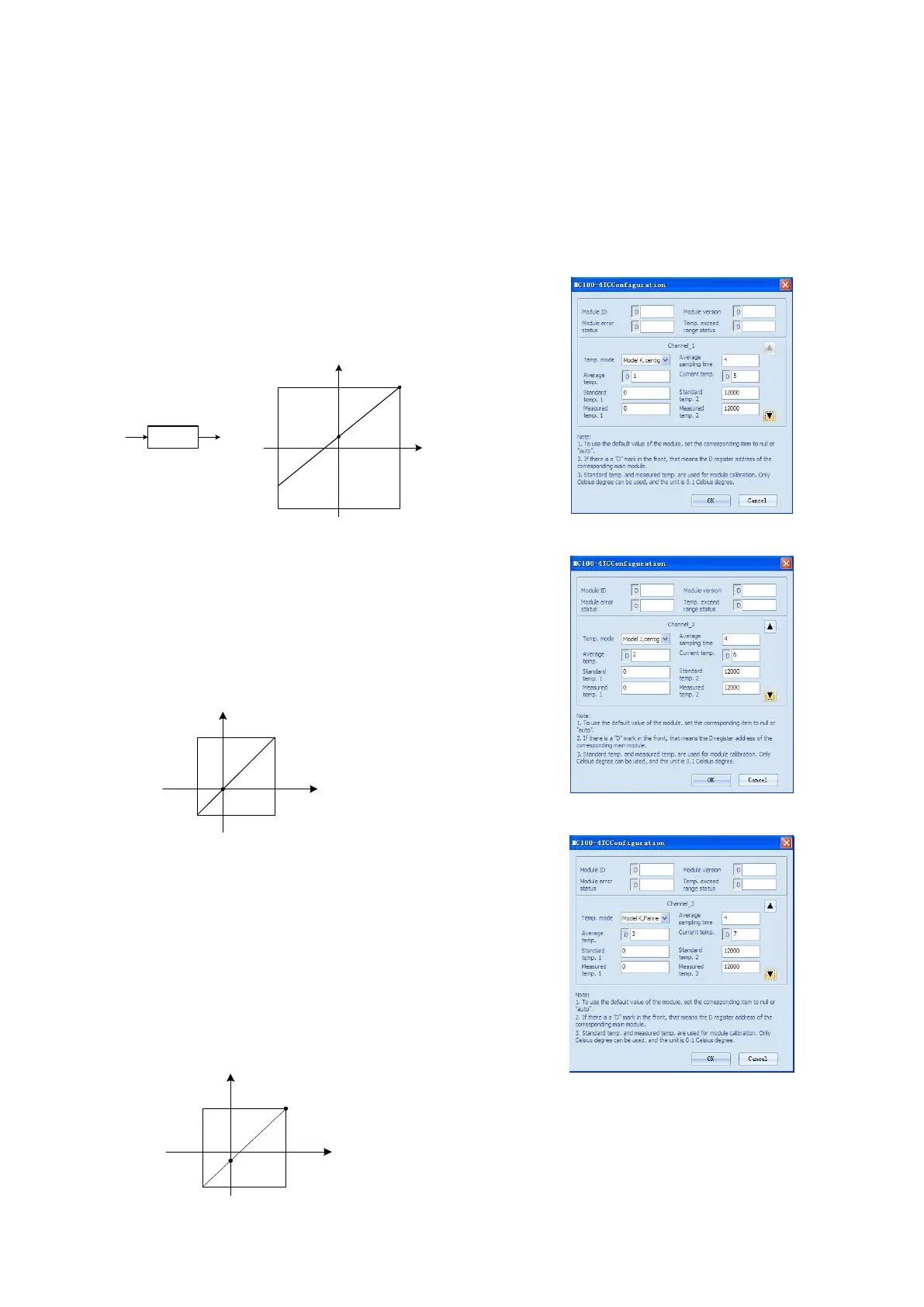
Example: Connect channels 1 and 2 of MC100-2TC/4TC respectively to K
and J type thermocouples with Celsius output, connect channel 3 to K type
thermocouples with Fahrenheit output, and close CH4. Set the average
sampling times of CH1 ~ CH3 to 4, and use data registers D1 ~ D3 to receive
the average value.
The setting interface of output CH1 is shown in Figure 4-1. After the setting,
click the downward arrow button to continue to set CH 2 ~ CH4, whose
setting interfaces are shown in figures 4-2 ~ 4-4. For detailed software usage,
see MC200/100 Series PLC Programming Manual.
Figure 4-1 CH1 setting interface
Figure 4-2 CH2 setting interface
Figure 4-3 CH3 setting interface
 Loading...