2
12-digit AD conversion, 16-digit complement for storage
± (0.5% full range+1°C), water freezing point: 0°C/32°F
Between analog circuit and digital circuit: photocoupler.
Between analog circuit and input 24Vdc power: internal
isolation. Between analog channels: none
2.3 Buffer Memory
MC100-2TC/4TC exchanges data with the basic module through Buffer
Memory (BFM). After MC100-2TC/4TC is set through the host software, the
basic module will write data into MC100-2TC/4TC BFM to set the state of
MC100-2TC/4TC, and display the data from MC100-2TC/4TC on the host
software interface. See figures 4-1 ~ 4-8.
Table 2-3 describes the contents of the BFM of MC100-2TC/4TC.
Table 2-3 BFM contents
Average temperature of
CH1~CH4
Current temperature of
CH1~CH4
Sampling times respectively
for averages of CH1 ~ CH3
Note:
1. CH1 stands for channel 1; CH2, channel 2; CH3, channel 3, and so on.
2. Property explanation: R means read only. An R element cannot be
written. RW means read and write. Reading from a non-existent
element will get 0.
3. BFM#200 ~ BFM#203: current temperature. Unit: 0.1°C/°F (depending on
the value of BFM#600). The average value are stored in
BFM#100-BFM#103.
4. BFM#300 error status information is shown in Table 2-4.
Table 2-4 BFM#300 status information
b1 or b2 is ON, AD conversion
of all channels stopped
24Vdc power supply failed
AD converter or other
hardware faulty
Digital output after AD
conversion outside the range
of -2048 ~ 2047
5. BFM#301 error status information is shown in Table 2-5.
Table 2-5 BFM#301 status information
CH1 temperature lower than lower limit
CH1 temperature higher than upper limit
CH2 temperature lower than lower limit
CH2 temperature higher than upper limit
CH3 temperature lower than lower limit
CH3 temperature higher than upper limit
CH4 temperature lower than lower limit
CH4 temperature higher than upper limit
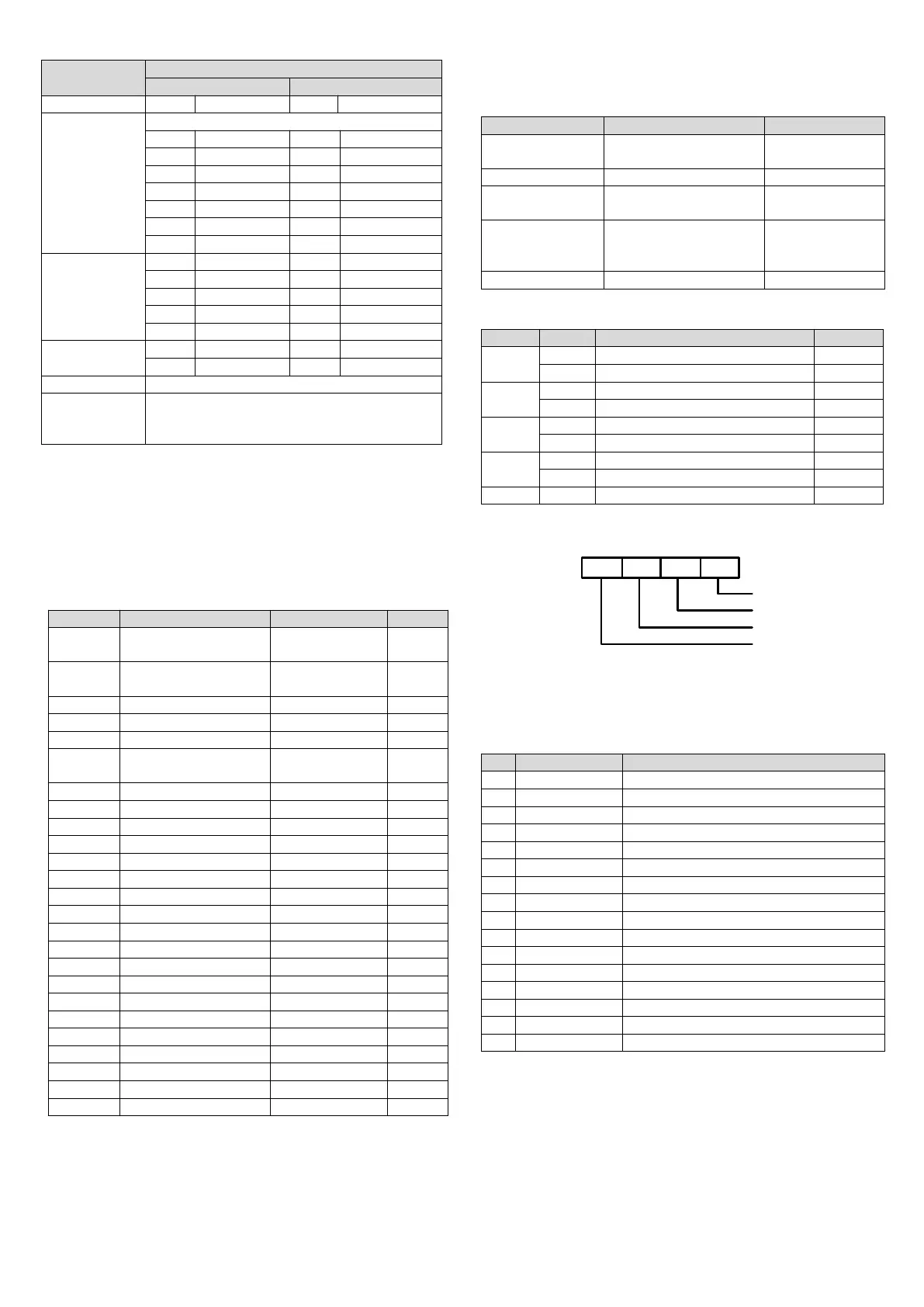
6. BFM#600: channel mode selection, used to set the working modes of CH1
~ CH4. See Figure 2-1 for their correspondence.
×
4
0
x
×
3
×
2
×
1
Working mode for CH1
600#
Working mode for CH2
Working mode for CH3
Working mode for CH4
Figure 2-1 Mode setting element vs. channel
The exact meaning of the X in the channel mode is shown in Table 2-6. The
conversion time of every channel is 240ms. When a channel is set closed, it
will not perform AD conversion, thereby reducing the total conversion time.
Table 2-6 Meaning of X in channel mode
K type thermocouple. Digital signal unit: 0.1°C
K type thermocouple. Digital signal unit: 0.1°F
J type thermocouple. Digital signal unit: 0.1°C
J type thermocouple. Digital signal unit: 0.1°F
E type thermocouple. Digital signal unit: 0.1°C
E type thermocouple. Digital signal unit: 0.1°F
N type thermocouple. Digital signal unit: 0.1°C
N type thermocouple. Digital signal unit: 0.1°F
T type thermocouple. Digital signal unit: 0.1°C
T type thermocouple. Digital signal unit: 0.1°F
R type thermocouple. Digital signal unit: 0.1°C
R type thermocouple. Digital signal unit: 0.1°F
S type thermocouple. Digital signal unit: 0.1°C
S type thermocouple. Digital signal unit: 0.1°F
7. BFM#700 ~ BFM#703: average sampling times setting. Range: 1 ~ 256. If
the setting is outside this range, the value will be reset to the default 8.
5. BFM#900 ~ BFM#915: channel characteristics setting data register. Use
two points to define the channel characteristic. D0 and D1 are the channel
digital output, in the unit of 0.1°C. A0 and A1 are the actual temperature input
of the channel, also in the unit of 0.1°C. Each channel occupies 4 words.
You can change the channel characteristic by changing D0 and D1. The
setting range of D0 is -1000~1000 (0.1°C); D1, 11,000~13,000 (0.1°C). If the
setting is outside this range, MC100-2TC/4TC will not accept it, but maintain
the original valid setting.
Note that the characters are all in 0.1°C unit. Convert Fahrenheit parameters
 Loading...