23
are supported, as shown in table 3-1. The longest frame can operate continuously with 50 BFM cells
(RTU) or 25 BFM cells (ASCII). The read and write addresses of the standard Modbus correspond to
those defined by BFM.
Table 3-1 Function code table
Write a single coil (M element)
Write a single register (BFM)
Write multiple registers (BFM)
Before power, the slave station address and working mode should be set by slave station address knob
and dial switch. The address and communication format of the slave station will not be valid until the next
time the power is switched on. The positions of MODBUS address setting knob and dial switch are shown
in figure 1-1.
Through the MODBUS address setting knob, the addresses of slave stations within 1-9 can be set.
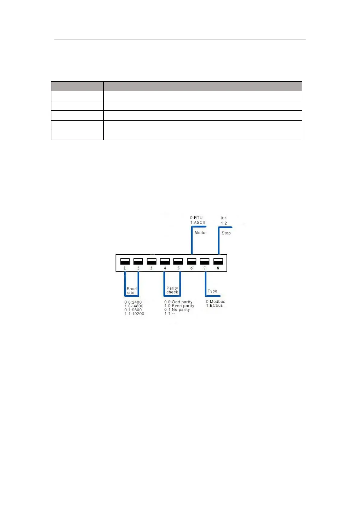
Use the dial switch to set the communication format.
The Settings of the dial switch are shown in figure 3-1.
Figure 3-1 DIP switch description
When Modicon Modbus protocol is used to read and write MTC, the logical address of Modicon Mobus
data is equal to the BFM address plus 1. For example, when the current value of the first channel is read,
the BFM address is 100, and the logical address of Modicon data is 4:101.
3.2 MCbus communication protocol
MCbus communication protocol is a small PLC network protocol developed by MEGMEET. MTC USES
MCbus communication protocol when matching with MEGMEET series PLC modules.
Note: 1. Users can download the programming software X_Builder at www.megmeet.com.
2. MCbus protocol can be referred to "MC series small programmable controller programming
manual".
3.2.1 Wiring
 Loading...