Do you have a question about the MEIG SLM 320 and is the answer not in the manual?
Provides essential safety guidelines for users to ensure personal safety and protect equipment.
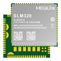
Overview of the SLM320 module, its supported network standards, and primary applications.
Highlights the main technical features and capabilities of the SLM320 module.
Illustrates the internal architecture and main functional blocks of the SLM320 module.
Details the evaluation kit provided by MeiG for testing and using the SLM320 module.
Describes the overall LCC+LGA interface and functional interfaces provided by the SLM320.
Details the pin configuration and layout of the SLM320 module.
Defines the function and electrical characteristics of each pin on the SLM320 module.
Explains the power supply requirements and reference design for the SLM320 module.
Covers the procedures and circuits for powering on and starting the SLM320 module.
Describes hardware and AT command methods for resetting the SLM320 module.
Details the USIM/SIM card interface, including hot-plugging and configuration.
Explains the USB 2.0 interface for AT commands, data transfer, and debugging.
Describes the main and debug serial ports, including pinouts and logic levels.
Explains how to use network status indicator pins for module status monitoring.
Details methods for entering flight mode, sleep mode, and ultra-low power mode.
Describes the two-way 12-bit analog-to-digital conversion interface.
Explains the USB_BOOT port for forced download mode and module upgrading.
Overview of the SLM320's integrated GPS chip supporting multiple navigation systems.
Details the performance specifications of the GNSS receiver, including start times and accuracy.
Provides recommendations for antenna placement and signal routing for GNSS.
Guidance on connecting active and passive antennas for GNSS functionality.
Introduces the three antenna pins and impedance matching for optimal RF performance.
Presents reference circuits and design considerations for RF antenna connections.
Details the requirements for antenna receiving and transmission parameters.
Specifies the RF transmission power levels for various frequencies and bands.
Provides the RF reception sensitivity values across different frequencies and bands.
Lists the operating uplink (UL) and downlink (DL) frequencies for different network bands.
Outlines the Over-The-Air (OTA) antenna performance requirements.
Defines the maximum voltage limits the module can withstand without damage.
Specifies the recommended operating and storage temperature ranges for the module.
Details the electrical characteristics for digital I/O signal levels.
Provides power consumption data for various operating states like power-off, sleep, and dormant.
Outlines environmental test conditions and requirements for module reliability.
Covers ESD protection considerations and performance parameters for the module.
Provides detailed mechanical dimensions of the SLM320 module in millimeters.
Shows the recommended PCB footprint for mounting the SLM320 module.
Illustrates the top view of the SLM320 module with labels and markings.
Shows the bottom view of the SLM320 module, highlighting the LGA/LCC pads.
Specifies conditions for storing the SLM320 modules to maintain quality.
Presents the recommended reflow soldering temperature curve for module assembly.
Describes the tray packaging method used for the SLM320 modules.
Lists related documents and specifications for the SLM320 module.
Provides a glossary of abbreviations and their English descriptions.
Details FCC requirements and rules applicable for module certification.
Outlines the operational conditions and integrated features of the SLM320 module.
Describes instructions and limitations for integrating the module into host devices.
Notes that specific antenna trace designs are not applicable.
Addresses FCC RF exposure limits and installation guidelines for safe operation.
States that the module does not come with a standard antenna.
Covers FCC labeling requirements and information for compliance.
Provides guidance on test modes and coordination for testing.
Clarifies the disclaimer for Part 15 Subpart B testing and responsibilities.
Specifies the need for user manual reference and special power supply for testing.
| Brand | MEIG |
|---|---|
| Model | SLM 320 |
| Category | Wireless modules |
| Language | English |