MeiG_SLM320_Hardware Design Manual
MeiG Smart Technology Co., Ltd
by default;
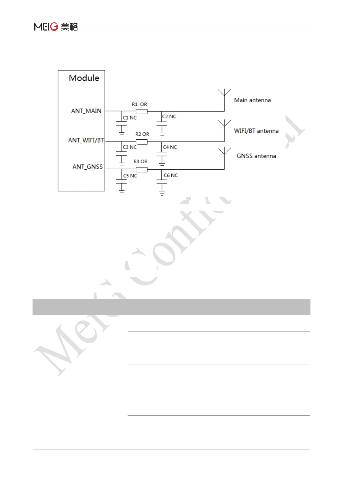
4. PCB layout, Module RF port to the antenna between lines as short as possible, and need to plate
factory for RF line do 50 Ω impedance control.
Figure 19 RF reference circuit
5.3 Installation of antenna
5.3.1 Antenna requirements
The requirements of antenna receiving antenna are shown in the following table:
Table 20 Antenna requirements
Type Requirement
GSM/TDD-LTE/FDD-LTE
VSWR: < 2
Gain (dBi): 1
Maximum Inupt (W): 2W
Input impedance (ohm): 50
Polarization Type: vertical direction
Cable insertion loss: < 1.5dB
(GSM900/1800 ; LTE B1/B2/B3/B4/B5/B8/B34/B39)
Cable insertion loss: < 2dB
WIFI/BT VSWR: < 2


 To Next Page