EasyManua.ls Logo

Meler micron 20 User Manual

Default Icon
2 pages
To Next Page IconTo Next Page
Page #1 background imageLoading...
Page #1 background image
QUICK START GUIDE: MICRON GEAR SERIES
Warning: Risk of electrical shock. Carelessness may produce injury or death.
Warning: Hot zone with high temperatures. Risk of burns. Use thermal
protective equipment.
Warning: System under pressure. Risk of burns or particle projection. Use
thermal protective equipment and googles.
Warning: Important information for the correct use of the system. May include
one or several of the previous hazards, and therefore must be kept in mind to
avoid damage and injury.
Components, options and accessories
Mounting the equipment
Dimensions/ Free space
Electrical power connection
Warning: The Micron gear series melters are equipment with current technology and with
certain foreseeable risks. Therefore, only allow qualified personnel with sufficient training and
experience to use, install or repair this equipment.
In case of doubts in the moment of installation, refer to the corresponding instructions
manual.
If you want this guide in other language, see the website:
http://www.meler.eu
ITEM DESCRIPTION DIMENSIONS
A
EQUIPMENT LENGTH
5L 730mm
10L 730mm
20L 730mm
35L 740mm
B EQUIPMENT WIDTH
5L 360mm
10L 360mm
20L 400mm
35L 450mm
C
EQUIPMENT HEIGHT
5L 630mm
10L 630mm
20L 670mm
35L 830mm
D EQUIPMENT HEIGHT WITH LID OPEN
5L 775mm
10L 885mm
20L 1025mm
35L 1215mm
E EQUIPMENT LENGTH WITH ELECTRICAL CABINET OPEN
5L 840mm
10L 920mm
20L 925mm
35L 990mm
F
LENGTH OF THE EQUIPMENT WITH BRACKET FOR
ELECTRIC CABINET VARIABLE FREQUENCY DRIVES IN
LOWERED POSITION
5L 1200mm
10L 1280mm
20L 1285mm
35L 1355mm
Fitting straight short
Warning light
By-pass valve
Low level detector Automatic feeder
Air dryer system
Hose
LN ~ 230V 50/60 Hz + PE
3N ~ 400V 50/60 Hz + PE
3 ~ 230V 50/60 Hz + PE
MODEL No. OUTPUT 1 PHASE 3 PHASES + N
230 VAC 400 VAC Y
1 PUMP 2 PUMPS 1 PUMP 2 PUMPS
Micron 5
2 25.17 A 31.00 A 12.87 A 16.70 A
4 35.60 A 41.42 A 12.87 A 21.91 A
6 46.04 A - 12.87 A -
Micron 10
2 29.52 A 35.34 A 17.23 A 16.70 A
4 39.95 A 45.77 A 17.23 A 21.91 A
6 50.39 A - 17.28 A -
Micron 20
2 27.39 A 37.51 A 19.41 A 16.70 A
4 42.13 A 47.95 A 19.41 A 21.91 A
6 52.56 A - 19.41 A -
Micron 35
2 38.21 A 44.03 A 16.30 A 16.70 A
4 48.65 A 54.47 A 21.52 A 21.91 A
6 59.08 A - 26.74 A -
ITEM MICRON 5 MICRON 10 MICRON 20 MICRON 35
A 96 mm 96 mm 96 mm 96 mm
B 377,5 mm 462,5 mm 462,5 mm 529,5
C 569,5 mm 654,5 mm 654,5 mm 721,5 mm
D 75 mm 75 mm 75 mm 75 mm
E 328,5 mm 328,5 mm 370,5 mm 422,5 mm
F 15 mm 15 mm 15 mm 15 mm
G 13 mm 13 mm 13 mm 13 mm
M8
M8
Wheels
B
E
F
A
C
D
Nota: To calculate the space necessary to install the equipment in terms of its length, you must
add at least 280 mm to the measurements indicated in the table in order to be able to open the
distributor’s filter-purger access door.
APROBACION
Ing. Fabricación
Calidad
Producción
Nombre:
Nombre:
Nombre:
MANTENER ORDEN Y LIMPIEZA
EN EL PUESTO Y
EN LA LINEA EN GENERAL
GUANTES
ZAPATOS
GAFAS
OTROS
EQUIPO
DE SEGURIDAD
Formación requerida
operario
Nº de Pokayokes
Piezas en proceso
Calibración requerida
328,5
654,5
13
15
96
462,5
Ø9
75
A B
G
F
E
D
C
Pneumatic and hose connection
1 3
5
2 4
6
P= 0 bar
1
4
3
9/16“
6 x
3
Ø6mm
P
max
= 6 bar
2
1
2
Ø6-12mm
Focke Meler Gluing Solutions, S. A.
P.I. Los Agustinos, calle G, nave D-43
E - 31160 ORCOYEN Navarra (España)
Tel.: + 34 948 351 110
Fax: + 34 948 351 130
e-mail: info@meler.es
www.meler.eu
GLUING SOLUTIONS
MA-5079-ENG V0718
Electrical power connection
3
L3 N PE L1 L2 L3 N PE
LN ~ 230V 50/60Hz + PE
3N ~ 400V 50/60Hz + PE
3
L1 L2 L3 PE
3~230V 50/60Hz + PE
WITHOUT NEUTRAL
Question and Answer IconNeed help?

Do you have a question about the Meler micron 20 and is the answer not in the manual?

Meler micron 20 Specifications

General IconGeneral
CategoryWater Pump
ModelMicron 20
Max Flow Rate20 l/min
Voltage220-240 V
Frequency50 Hz
Inlet/Outlet Size1 inch

Summary

Micron Gear Series Components and Accessories

Safety Warnings and Indicators

Details critical safety warnings related to electrical shock, hot zones, and system pressure, along with warning lights.

System Components Overview

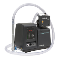
Identifies key components like air dryer system, low level detector, automatic feeder, hose, and by-pass valve.

Equipment Mounting and Dimensions

Mounting Guidelines

Provides instructions and diagrams for mounting the equipment, including necessary clearance space.

Dimensional Specifications

Lists detailed measurements (A-F) for different Micron Gear Series models for installation planning.

Electrical Power Connections

Power Connection Types

Details connection requirements for 230V and 400V systems, including single and three-phase options.

Current Rating Table

Provides a table of electrical current ratings for various Micron models based on phase and number of pumps.

Pneumatic and Hose Connections

Pneumatic System Setup

Illustrates pneumatic connection requirements, including pressure limits and hose size.

Starting Up the Melter Equipment

Initial Startup Procedure

Outlines the essential steps for starting the melter equipment, including power activation.

Mode of Operation Selection

Explains how to select the appropriate operating mode for internal/external control of pumping and speed.

Pump Control Card and Settings

Control Card Overview

Details the pump control card, its LEDs, and input/output functions for operation.

Speed Working Adjustment

Guides on how to adjust the working speed using the control card's buttons and display.

Temperature Adjustment and Safety

Temperature Adjustment Process

Describes how to modify temperature set points and select display units (°C/°F).

Overheating and Standby Settings

Explains how to set values for overheating protection and standby mode to prevent damage.

External I/O Connections

General I/O Connectivity

Details optional external connections for signals like motor start and output disabled.

Specific Signal Wiring

Provides wiring guidance for motor start signals, speed set points, and low-level detection.

Failures Output Configuration

Explains how to connect the failures output from the pump control card.

Related product manuals