Home
Mellanox Technologies
Gateway
SX6025
Mellanox Technologies SX6025 - User Manual
8 pages
Manual
Specs
Ask a question
Save Page as PDF
To Next Page
To Next Page
Loading...
www
.mellanox.com
Mellano
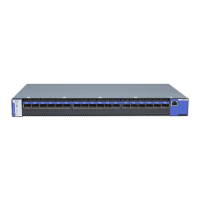
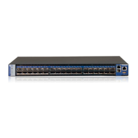
x InfiniBand
1U Switch Systems
Quick Installation Guide
Models: SX6015, SX6018, SX6025, SX6036,
SX6036G
2
Table of Contents
Main Page
Pay Attention
2
Package Contents
2
LED Assignments
8
Need help?
Do you have a question about the Mellanox Technologies SX6025 and is the answer not in the manual?
Ask a question
Mellanox Technologies SX6025 Specifications
Print Specification
General
Data Transfer Rate
56 Gbps per port
Form Factor
1U
Throughput
1.44 Tbps
Management
CLI, SNMP
Compatibility
InfiniBand
Related product manuals
Mellanox Technologies SX6005
114 pages
Mellanox Technologies SX6015
8 pages
Mellanox Technologies SX6018
8 pages
Mellanox Technologies SX6036
8 pages
Mellanox Technologies SX6036G
8 pages
InfiniBand X
96 pages