Cooper Lighting and Security
Wheatley Hall Road,
Doncaster,
South Yorkshire,
DN2 4NB
Tel: 01302 321 541
www.cooper-ls.com
INSTALLATION
MAB 800 Specification
Order Codes
Supply Voltage 18 - 30 V DC
Cable Size 0.5 - 2.5mm
Mounting Hole Centres 50 - 80mm
²
Recommended cable types FIRETUF,FP200 or MICC
MAP820 Analogue Addressable Photoelectric Smoke Detector
MAI810 Analogue Addressable Ionisation Smoke Detector
MAH830 Analogue Addressable Heat Detector
MAOH850 Analogue Addressable Photo/ThermalDetector
Doc Ref: PINST800A ISS E
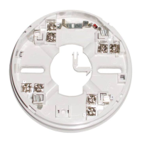
Wiring Hints
! Each terminal is suitable for clamping up to 2 wires
! Clamping of 2 wires of very different diameters under
one screw is not recommended.
! Suitable for mounting to mounting boxes with 50-
80mm fixing centres.
General
If difficulty is experienced when mounting the detector, this may
be due to the following:
! Wiring causing an obstruction - move or shorten wires.
! Although the base is tolerant to uneven mounting
surfaces, a very uneven surface may cause the base
to deform when the mounting screws are tightened
down - loosen screws to reduce this or slide base to a
more flat position.
WARNING: DO NOT USE HIGH VOLTAGE TESTERS
WHEN DETECTORS OR CONTROL PANEL
ARE CONNECTED TO THE SYSTEM.
Utilising Locking Tab
1
2
The mounting base includes an
optional feature to prevent the
removal of the detector without
the use of a tool.
1. Remove the standard fit
retaining clip.
2. Insert the locking clip which
is located at the centre of the
base as shown.
Mount the detector onto the base as described in Detector
Installation (see over) and rotate fully clockwise until it finally
clicks.
The detector is now locked into position. Remove by utilising a
suitable tool (eg a thin screwdriver) into the hole in the detector
cover. Gently push the tool into the detector and rotate anti-
clockwise.
+
Remote
Indicator
LED
(optional)
+VIN
- VE COM OUT
2
4
1
3
2
4
1
3
Earth screen of cable to be continuous between detectors
S+
F
F+
S
_
_
_
_
_
_
_
_
_
_
DF6000
Analogue Addressable
Fire Alarm Panel
Loop Start
Loop Finish
- VE COM IN
Attention: If using the outer connection on terminal2, ensure the operation of the switch is not impeded and that there no shorts between
terminal 2 and the switch contact.
Ensure that the cable does not short onto the contact