EasyManua.ls Logo

MerCs Strider M4 V2 Series - User Manual

MerCs Strider M4 V2 Series
21 pages
Print Icon
To Next Page IconTo Next Page
Loading...
1
02 4047 0777 www.mercs.com.au02 4047 0788
MerCs Pty Ltd, 55 Pendlebury Rd, Cardi, NSW, 2285, Australia | 2019 V1.1
Two pulse output indicates real time energy measurement. An RS485 outp ut allows remote monitoring from another display or a computer.
The Unit can measure and display: The unit has password protected set up screens for:
Unit Characteristics
Line voltage and THD% (total harmonic distortion) of all phases
Line Frequency
Currents, Current demands and current THD% of all phases
Power, maximum power demand and power factor
Active energy imported and exported
Reactive energy imported and exported
Changing password
Supply system selection 1p2w, 3p3w, 3 p 4w
Demand Interval time
Reset for demand measurements
Pulse output duration
User Manual
IntroductionApplications
Features
The unit measures and displays the characteristics of single phase two wires (1p2w), three phase
three wires (3p3w,) and three phase four wires (3p4w) supplies, including voltage, frequency,
current, power ,active and reactive energy, imported or exported. Energy is measured in terms
of kWh, kvarh. Maximum demand current can be measured over preset periods of up to 60min-
utes. In order to measure energy, the unit requires voltage and current inputs in addition to the
supply required to power the product. The requisite current input(s) are obtained via current
transformers (CT). This meter can be congured to work with a wide range of CTs, giving the unit
a wide range of applications. Built-in interfaces provides pulse and RS485 Modbus RTU outputs.
Conguration is password protected. This unit can be powered from a separate auxiliary (AC or
DC) supply. Alternatively it can be powered from the monitored supply, where appropriate.
Strider M4 V2
Multi-Function Energy Meter
ME-PM-M4-5
Measures kWh Kvarh, KW, Kvar, KVA, P, F, PF, Hz, dmd, V, A, THD, etc.
• Bi-directional measurement IMP & EXP
• Two pulse outputs
• RS485 Modbus
• Din rail mounting 35mm
• 1/5A CT connection
• Accuracy Class 0.5s
Main Switchboards
Control Panels
Sub Circuits
Air Conditioning Systems
Solar panel installations
Question and Answer IconNeed help?

Do you have a question about the MerCs Strider M4 V2 Series and is the answer not in the manual?

Overview

The MerCs Strider M4 V2 (ME-PM-M4-5) is a multi-function energy meter designed for safe, productive, and reliable measurement of electrical characteristics. This user manual provides comprehensive details on its features, operation, and installation.

Function Description

The Strider M4 V2 measures and displays various electrical characteristics for single-phase two-wire (1p2w), three-phase three-wire (3p3w), and three-phase four-wire (3p4w) supplies. It monitors voltage, frequency, current, power (active and reactive), and energy (imported or exported). Energy is measured in kWh and kvarh. The device can also measure maximum demand current over preset periods of up to 60 minutes.

The unit requires voltage and current inputs, in addition to the supply needed to power the product. Current inputs are obtained via Current Transformers (CTs), and the meter can be configured to work with a wide range of CTs, making it suitable for diverse applications. It features built-in interfaces for pulse outputs and RS485 Modbus RTU communication. Configuration settings are password protected. The unit can be powered from a separate auxiliary (AC or DC) supply or from the monitored supply.

Important Technical Specifications

  • Measurements: kWh, kvarh, kW, kvar, kVA, P, F, PF, Hz, dmd, V, A, THD, etc.
  • Measurement Type: Bi-directional (Import & Export)
  • Outputs: Two pulse outputs, RS485 Modbus RTU
  • Mounting: DIN rail (35mm)
  • CT Connection: 1/5A
  • Accuracy Class: 0.5s
  • Voltage Inputs: 4-way fixed connector with 2.5mm² stranded wire capacity. Line frequency measured from L1 or L3 voltage.
    • Phase to neutral voltages: 100 to 289V a.c. (not for 3p3w supplies)
    • Voltages between phases: 173 to 500V a.c. (3p supplies only)
    • Voltage THD%: for each phase to N (not for 3p3w supplies) and between phases (three-phase supplies only)
  • Current Inputs: Three current inputs (six physical terminals) with 2.5mm² stranded wire capacity for external CTs. Nominal rated input current 5A or 1A a.c. Rms.
    • Current THD% for each phase
  • Power Factor and Frequency:
    • Frequency in Hz
    • Instantaneous Power: 0 to 3600 MW (Active), 0 to 3600 MVAr (Reactive), 0 to 3600 MVA (Volt-amps)
    • Maximum demanded power and neutral demand current (for three-phase supplies only) since last Demand reset.
  • Energy Measurements:
    • Imported/Exported active energy: 0 to 9999999.9 kWh
    • Imported/Exported reactive energy: 0 to 9999999.9 kVArh
    • Total active energy: 0 to 9999999.9 kWh
    • Total reactive energy: 9999999.9 kVArh
  • Accuracy:
    • Voltage: 0.5% of range maximum
    • Current: 0.5% of nominal
    • Frequency: 0.2% of mid-frequency
    • Power factor: 1% of unity (0.01)
    • Active/Reactive/Apparent power: ±1% of range maximum
    • Active energy (Wh): Class 0.5S IEC 62053-21
    • Reactive energy (VArh): ±1% of range maximum
    • Total harmonic distortion: 1% up to 31st harmonic
    • Response time to step input: 1s, typical, to >99% of final reading, at 50 Hz
  • Auxiliary Supply: Two-way fixed connector with 2.5mm² stranded wire capacity. 85 to 275V a.c. 50/60Hz ±10% or 120V to 380V d.c. ±20%. Consumption < 10W.
  • Interfaces for External Monitoring:
    • RS485 communication channel (Modbus RTU protocol)
    • Relay output for real-time measured energy (configurable)
    • Pulse output 3200imp/kWh (not configurable)
  • Pulse Output: Configurable to represent kWh or kVArh. Rates: 1 pulse per 0.01, 0.1, 1, 10, 100, 1000 kWh/kVArh. Pulse width: 200/100/60 ms. Relay Rating: 240V ac 50mA.
  • RS485 Output: Baud rates: 2400, 4800, 9600, 19200, 38400. Parity: none (default) / odd / even. Stop bits: 1 or 2. Network address: 1 to 247.
  • M-Bus Address: Primary address: 001 to 250. Secondary address: 00 00 00 01 to 99 99 99 99.
  • Environment:
    • Operating temperature: -25°C to +55°C
    • Storage temperature: -40°C to +70°C
    • Relative humidity: 0 to 95%, non-condensing
    • Altitude: Up to 3000m
    • Warm up time: 1 minute
    • Vibration: 60068-2-6, 2g
    • Shock: 30g in 3 planes
  • Mechanics:
    • DIN rail dimensions: 72 x 94.5 mm (WxH) per DIN 43880
    • Mounting: DIN rail (DIN 43880)
    • Sealing: Ip51 (indoor)
    • Material: Self-extinguishing UI94 V-0

Usage Features

  • Start-up Screens: The device performs a self-test upon startup, displaying software version information and indicating if the test passes. After a short delay, it shows active energy measurements.
  • Navigation: Four buttons (U/I ESC, M, P, E) are used for navigation and selection.
    • U/I ESC: Selects Voltage and Current display screens. In Set-up Mode, acts as "Left" or "Back."
    • M: Selects Frequency and Power factor display screens. In Set-up Mode, acts as "Up."
    • P: Selects Power display screens. In Setup Mode, acts as "Down."
    • E: Selects Energy display screens. In Setup mode, acts as "Enter" or "Right."
  • Set-up Mode: Accessed by pressing the E button for 3 seconds. It is password-protected (default '1000'). Incorrect passwords display "PASS Err."
  • Menu Option Selection: Use M and P buttons to select items. E confirms selection. Flashing items can be adjusted with M and P. U/I ESC returns to a higher menu level.
  • Number Entry: Digits are set individually from left to right using M and P buttons. E confirms each digit. U/I ESC exits the routine.
  • Change Password: Accessible in set-up mode. The new password screen appears with the first digit flashing.
  • DIT (Demand Integration Time): Sets the period (off, 5, 8, 10, 15, 20, 30, 60 minutes) over which current and power readings are integrated for maximum demand measurement.
  • Supply System Selection: Sets the type of power supply being monitored (1p2w, 3p3w, 3p4w). Default is 3p4w.
  • CT Settings: Configures the secondary current (CT2 1A or 5A) and CT Ratio (0001 to 9999).
  • PT Settings: Configures the secondary voltage (PT2 100 to 500V) and PT Ratio (0001 to 9999).
  • Pulse Output Configuration: Sets the energy type (kWh or kVArh) and pulse rate (e.g., 1 pulse per 10 kWh/kVArh).
  • Pulse Duration: Configurable pulse width (200, 100, or 60ms) for active or reactive energy.
  • Communication Settings: Configures RS485 Address, M-Bus Address, Baud Rate (2.4k, 4.8k, 9.6k, 19.2k, 38.4k), Parity (EVEN/ODD/NONE), and Stop bits (1 or 2).
  • Backlit Set-up: Sets the blue backlit lasting time (0/5/10/30/60/120 minutes). Option 0 means always on.
  • CLR (Clear): Resets the maximum demand value of current and power.

Maintenance Features

The manual emphasizes important safety information, advising users to familiarize themselves with the maintenance section before installation or servicing. It highlights the risk of danger and electric shock with corresponding symbols. The device is designed for indoor use (Ip51 sealing) and has a self-extinguishing material (UI94 V-0).
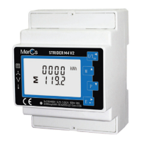
MerCs Strider M4 V2 Series Specifications

General IconGeneral
BrandMerCs
ModelStrider M4 V2 Series
CategoryMeasuring Instruments
LanguageEnglish