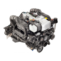
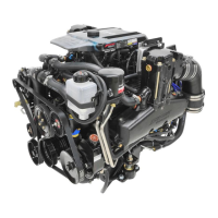
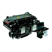
63500 EFI Bravo
OPERATION
POWER TRIM OPERATION - ZERO EFFORT CONTROL WITH
INTEGRAL TRIM SWITCH
The Bravo Heavy Duty Transom Assembly does not have an electri-
cal trim limit switch or trim position sender, therefore the following
precautions must be observed.
WARNING
Avoid personal injury or damage to stern drive unit. Without
a Trim Limit Switch, the drive unit can be trimmed up/out be-
yond the position where the drive unit has side support from
the gimbal ring at any throttle setting. It is highly recom-
mended that a mechanical (cable actuated) Trim Position Indi-
cator be used to provide important drive unit trim angle infor-
mation to the operator and that the Trim Indicator be marked
to clearly indicate the maximum up/out position where side
support is still provided. The drive unit should not be trimmed
to a position beyond gimbal ring side support at engine
speeds above 1200 rpm.
1 Trailering and Trimming UP/OUT Position: Press (Top) UP/OUT
portion of switch until drive unit reaches desired trim/trailering po-
sition.
NOTE: The word (Trim) is usually considered the first 20° OUT/UP
movement from vertical position.
2 Trim Drive Unit IN/DOWN Position: Press (Bottom) IN/DOWN
portion of switch until drive unit reaches desired trim position.

 Loading...


