ATTACHMENTS / CONTROL LINKAGE
90-855347R1 JANUARY 1999 Page 7-29
3. Place Ride-Guide yoke on pivot block and secure with 7/16 in. x 1-3/4 in. (11.1 mm
x 44.5 mm) bolt and locknut, as shown in Figures 1 and 2. Torque locknut to 10 Ib. ft.
(13.5 Nm), then back off 1/4-turn.
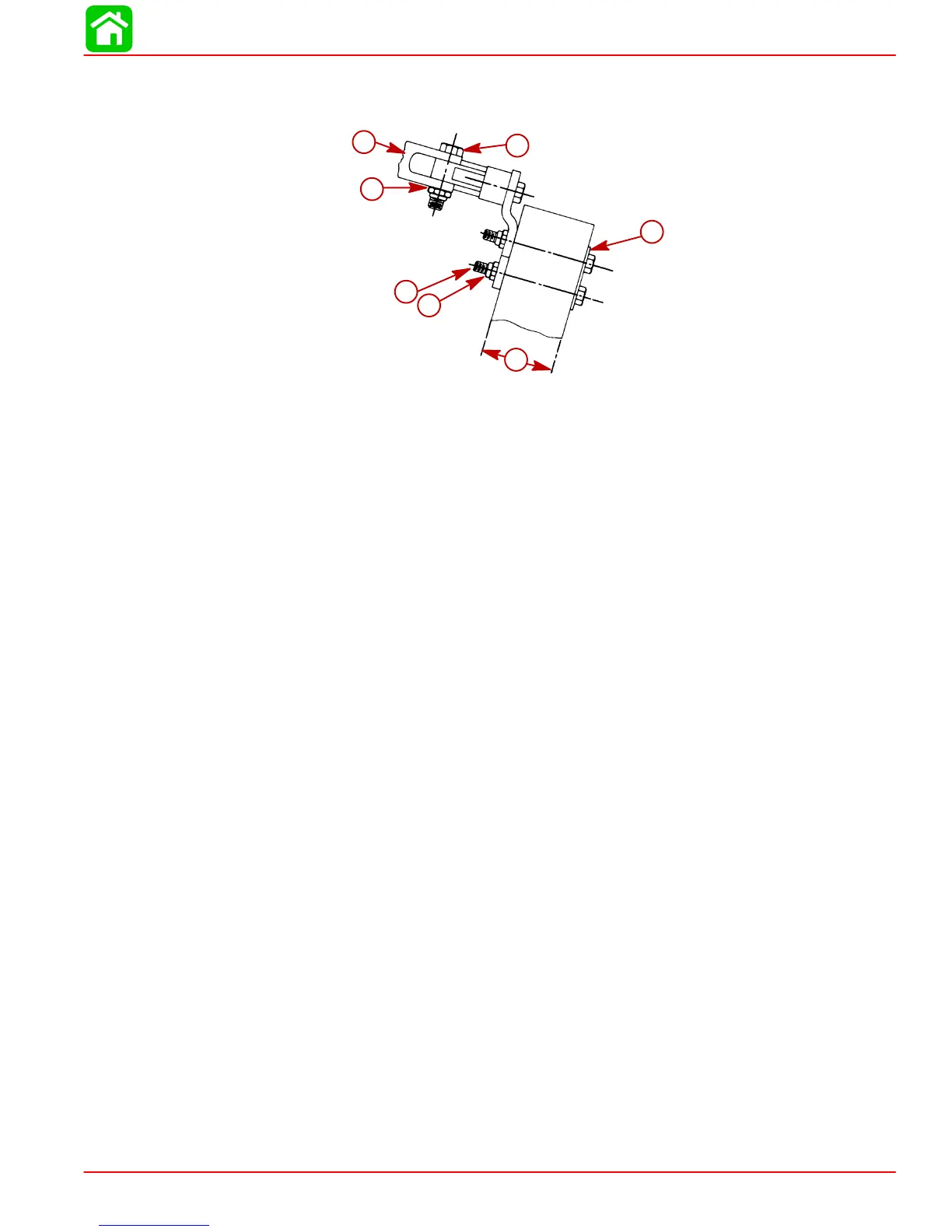
a
b
c
d
e
f
g
Figure 2
a-Transom Backing Plate
b-Bolt [5/16 in. x 3-1/4 in. (7.9 mm x 82.5 mm)]
c-Locknut [Torque to 10 lb. ft. (13.5 Nm)]
d-Ride-Guide Yoke Attaching Locknut [Torque to 10 lb. ft. (13.5 Nm)] Then
Back Off 1/4-Turn
e-2-3/8 in. (60.3 mm) Maximum Transom Thickness
f-Bolt [7/16 in. x 1-3/4 in. (11.1 mm x 44.5 mm)]
g-Ride-Guide Yoke
4. Install one cable tube jam nut onto steering cable tube. Place tab washer over
Ride-Guide yoke, then insert cable tube thru tab washer and yoke. Install second
cable tube jam nut onto cable tube but do not tighten at this time. (Figure 3)
5. Position transom attaching kit on transom as shown:
a. Determine centerline of outboard, then measure 15 in. (38.1 cm) over from this
centerline and draw a vertical line on transom. (Figure 1)