BA2070/03/1614
Error signal < 3.6 mA standard, when temperature sensor fails
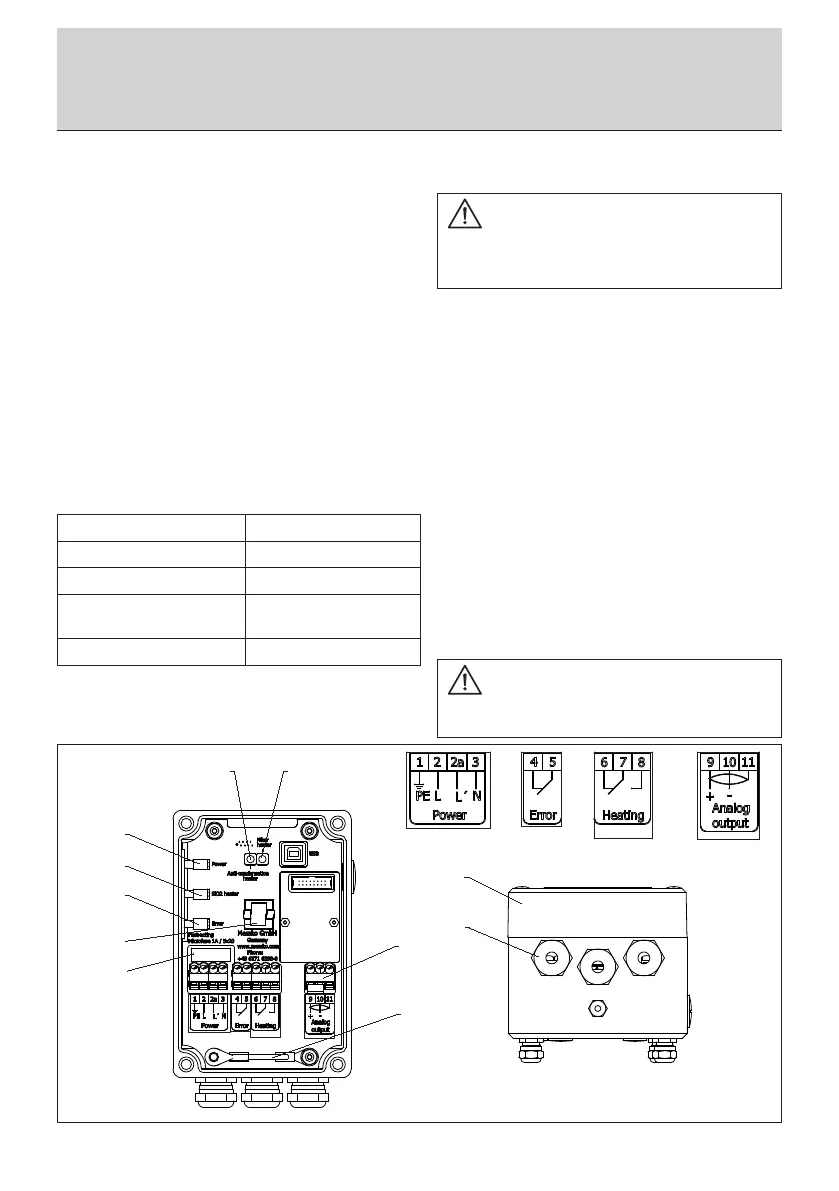
Relay outputs:
1 x change-over contact, signaling relay for regeneration
active/inactive
1 x normally closed contact, signaling relay for device faults
(failsafe)
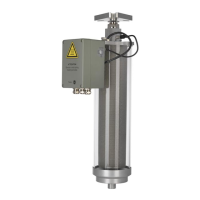
2.7 Filterheater (HT version)
We recommend the HT version, which features a heated high-
grade steel filter (Fig. 1/4) to ensure device functionality at
lowest temperatures, for applications in cold or arctic climates
(ambient temperature is continuously below -5°C over a period
of 20 days).
2.8 Status indicators
Three LEDs are installed on the side of the terminal box and 2
LEDs are installed on the board in the terminal box to indicate
the status of the device.
If an error occurs on the device, it is signaled by differently lit
or flashing LEDs (see chapter 5.4, table 1).
3 Installation
Depending on the particular application, the dehydrating
breather is mounted on the pipe to the oil conservator. A
suitable counter-flange must be installed on the pipe to mount
the dehydrating breather. Three connection types are listed
in the appendix (Fig. 4 to 6). During mounting, it is extremely
important to ensure that the included seal is installed between
the flanges. The DIN flange is secured with the 3 M12 screws
included. First, slightly tighten each of the screws in succession.
Then tighten these screws with a torque of 80 Nm. Wait
5 minutes and then tighten again to 80 Nm. The device is
available as an option with 2 side mounting rods. When equip-
ped with these rods, the device conforms to the installation
height h as per DIN 42 562.
In case of any further questions concerning the counter flange
or any customer-specific flanges, please do not hesitate to
contact us.
After mounting, the device can be aligned with a double scre-
wed fitting. To do this, loosen the nut (Fig. 1/2) and turn the
device to the desired position. Then tighten the nut again.
LED, green, outside (Fig.2/5) on Power voltage on
LED, yellow, outside (Fig.2/4) on Regeneration process active
LED, red, outside (Fig.2/3) Device error (flashing/on)
LED, yellow, inside (Fig.2/6) on Anti-condensation heater on
(heater of the terminal box)
LED, yellow, inside (Fig.2/7) on Filter heater on (HT version)
Fig. 2
CAUTION
The operating and installation requirements described in this
manual must be strictly complied with. If not, the device
may be damaged or may malfunction.
CAUTION
Do not unscrew the nut (Fig.1/12), since you may damage
the sealing of the device.
3 Installation
 Loading...