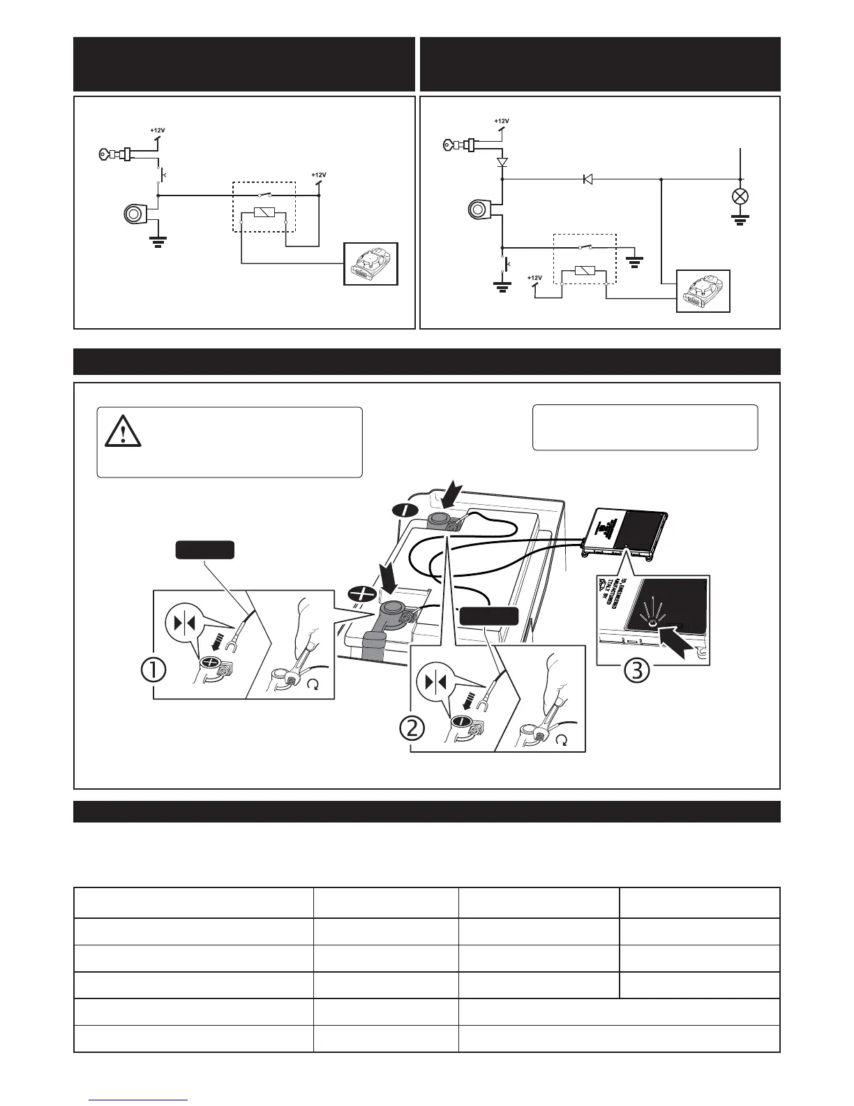
ATTENTION: First connect the fork contact
with RED SHEATH to the POSITIVE POLE
of the battery and, subsequently, the fork
contact with BLACK SHEATH to the NEGATIVE
POLE.
Verify that the led on the device ashes; if
not, check the connections and/or contact the
after-sales service
ALARM CONTROL UNIT: ELECTRICAL CONNECTIONS (connection to the battery)
CONTROL-OPERATED HORN
POSITIVE - LOCKED
ORIGINAL
COMMAND
ADDITIONAL
RELAY
TO
ROOT
COMMANDS
IGNITION
KEY BLOCK
IGNITION
KEY BLOCK
BROWN
LIGHT BLUE
HORN
HORN
ORIGINAL
COMMAND
ADDITIONAL
RELAY
BROWN
P600 DIODES
TO BE INSTALLED
TURN
SIGNALS
CONTROL-OPERATED HORN
NEGATIVE - LOCKED
5
TELEMATIC CONTROL UNIT: DIAGNOSTICS
The telematic control unit is equipped with a LED to provide diagnostic information and it is installed on top of the de-
vice. Based on the indications in the table below it is possible to verify the connectivity relative to the GSM to the GSM
& GPRS.
STATUS OF THE CONTROL UNIT DURING
REGISTRATION ON THE NETWORK
STATUS OF THE CONTROL
UNIT AFTER ACTIVATION
LED - RED LED - GREEN
Registration in progress Awake 1 fast ash
Registration completed Awake Always ON
Registration completed Sleep Mode 1 slow ash
Registration denied Awake Alternate fast RED and GREEN ash
Registration denied Sleep Mode Alternate slow RED and GREEN ash
BLACK
RED
 Loading...