ENGLISHen
12
a suitable dust collector attached to the saw.
The dust collector must comply with the data
stated in the technical specifications.
See to it that only as little as possible wood dust
will get into the environment:
– Remove wood dust deposit in the work area
(do not blow away!);
– fix any leakages on the dust collector;
– ensure good ventilation.
Hazard generated by modification of
the machine or use of parts not tested and
approved by the equipment manufacturer!
Assemble the machine in strict accordance with
these instructions.
Use only parts approved by the manufacturer.
This applies especially to:
– Saw belts (see "Technical Specifications" for
stock nos.);
– safety devices (see "Technical Specifications"
for stock nos.).
Do not change any parts.
Caution!
The use of other tools and accessories can result
in a risk of injury.
Hazard generated by machine defects!
Keep the machine and accessories in good
repair. Observe the maintenance instructions.
Before every use check the machine for
possible damage: before operating the machine
all safety devices, protective guards or slightly
damaged parts need to be checked for proper
function as specified. Check to see that all
moving parts work properly and do not jam. All
parts must be correctly installed and meet all
conditions necessary for the proper operation of
the machine.
Damaged protection devices or parts must be
repaired or replaced by a qualified specialist.
Have damaged switches replaced by a service
centre. Do not operate the machine if the switch
can not be turned ON or OFF.
Keep handles free of oil and grease.
Keep cutting tools clean and sharpened in able
to work better and safer.
Do not used damaged or deformed saw belts.
Risk of injury by noise!
Wear hearing protection.
Danger from blocking workpieces or
workpiece parts!
If blockage occurs:
1. switch machine off,
2. unplug mains cable,
3. wear gloves,
4. Clear the blockage using a suitable tool.
4.1 Symbols on the Machine
Danger!
Disregard of the following warnings may lead
to serious personal injury or material
damage.
Read instructions.
Wear protective goggles and ear
protectors.
Disconnect the mains plug before
starting any setting, maintenance or
repair work.
Do not direct the light beam into the
eyes of people or animals.
Wear ear protectors.
Height adjustment
Set saw belt track.
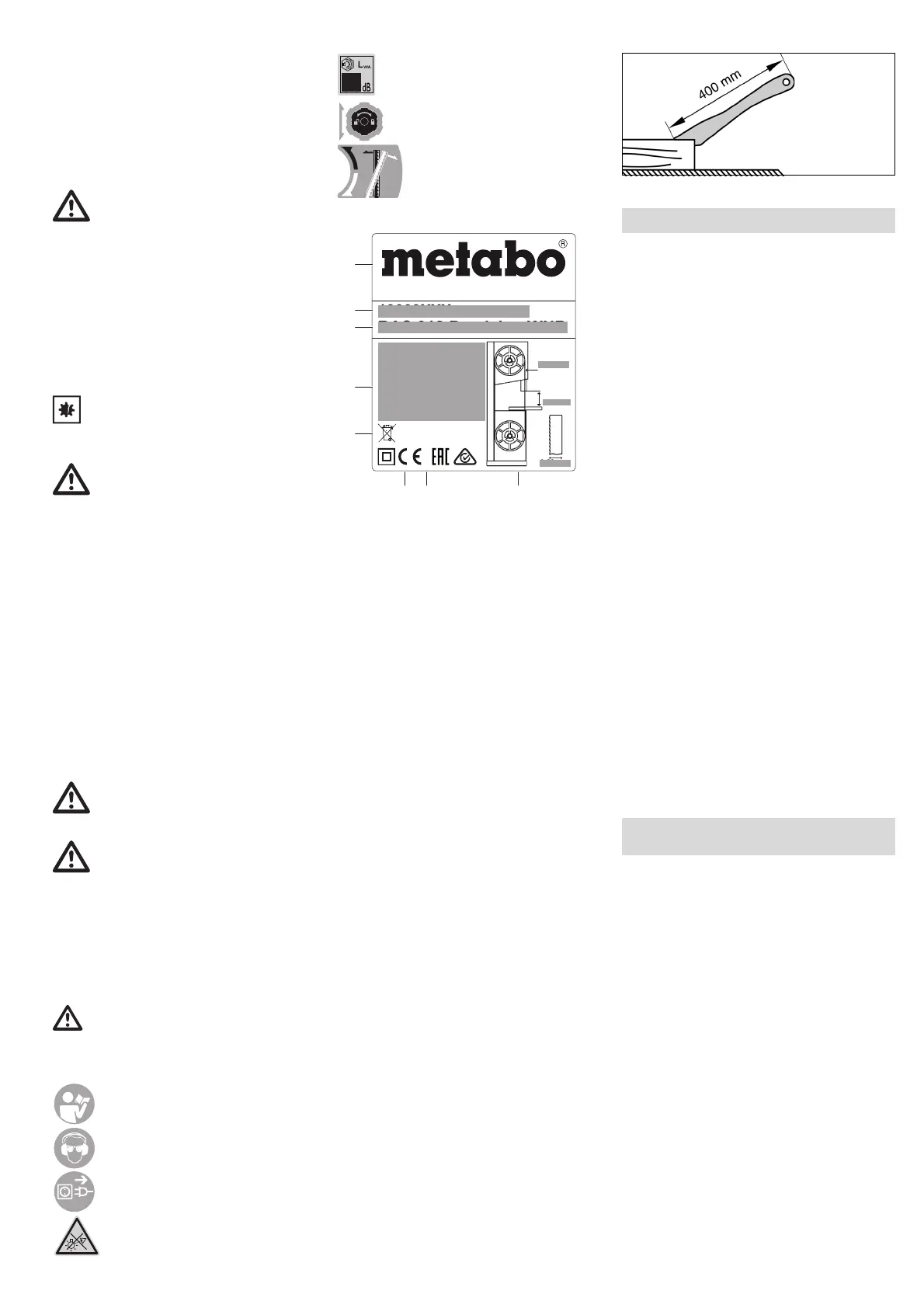
Information on the nameplate:
(a) Manufacturer
(b) Serial number
(c) Device designation
(d) Motor data (see also "Technical data")
(e) Disposal symbol – Device can be disposed of
via the manufacturer
(f) CE mark – This device fulfils the EU
Directives according to the Declaration of
Conformity
(g) Year of manufacture
(h) Dimensions of permitted saw belts
4.2Safety Devices
Upper belt guard
The upper saw belt guard (6) protects against
inadvertent contact with the saw belt and against
flying chips.
So that the upper saw belt cover provides sufficient
protection against contact with the saw belt, the
upper saw belt guide must be at least 3 mm from
the work piece.
Lower saw belt guard
The lower saw belt cover (7) protects against
inadvertent contact with the saw belt beneath the
sawing table.
The lower saw belt guard must be installed during
operation.
Housing doors
The housing doors (4) protect against contact with
the powered parts inside the saw.
The housing doors are equipped with interlocking
contacts. These turn the motor OFF when one
housing door is opened while the saw is running.
The housing doors must be closed while the
machine is in use.
Push stick
The push stick (8) serves as an extension to the
hand and protects against inadvertent contact with
the saw belt.
The push stick must always be used if the distance
between the saw belt and a rip fence is less than
120 mm.
The push stick must be held at angle of 20° … 30°
to the surface of the saw table.
Replace push stick if damaged.
See page 2 - 3.
1 On/off switch cutting line illumination
2On switch
3 Off switch
4Housing doors
5 Turn-lock fastener for opening the housing
door
6 Upper saw belt guard (on the upper belt guide)
7 Lower saw belt guard
8Push stick
9Hole in saw table
10 Saw table
11 Table insert
12 Chip extraction nozzle
13 Clamping screw (inclination setting saw table)
14 Saw table fastening screws
15 Rip fence screw on saw table
16 Fence guide extrusion
17 Parallel stop
18 Parallel stop clamping lever
19 Setting knob for saw belt tension
20 Mitre fence
21 Clamping handle on the mitre fence
22 Setting knob (height adjustment for the upper
belt guide)
23 Lock nut (height adjustment for the upper belt
guide)
24 Upper belt guide
25 Dust guard strip
26 Lock nut (for setting knob for the angle of the
upper band saw rollers)
27 Setting knob for the angle of the upper band
saw rollers
28 Upper thrust bearing
29 Screws for upper thrust bearing
30 Upper guide bearing
31 Screw for upper guide bearing
32 Lower thrust bearing
33 Screws for lower thrust bearing
34 Lower guide bearing
35 Screw for lower guide bearing
6.1 Unpacking
Unpack and transport saw with assistance from a
second person.
Do not lift or transport saw by holding the upper
saw belt guard (6).
6.2 Fix saw
For a safe stand, the saw has to be fixed on a
stable base.
Fasten to work bench:
1. Drill four holes in the supporting surface.
2. Put fixing bolts through the base plate and
secure with nuts.
6.3 Installing the Saw Table
1. Guide saw table (10) over the saw belt and
place on the saw table guide.
2. Fasten saw table to the saw table guide with
four screws (14) and washers - do not tighten,
align the saw table first (See chapter 6.4).
6.4 Align the saw table
The saw table needs to be aligned in two planes
– laterally so that the belt runs accurately in the
middle of the table insert;
– at right angles to the saw belt.
BAS 318 Precision WNB
YYYY
19009XXX
9997812345
Metabo- Allee 1, D-72622 Nuertingen,
Germany; Made in China
L=2240 mm
max.
170 mm
6-20 mm
1~ 220-240 V
I = 4,0 A
P 0,66 kW S1 100%
2
P 0,9 kW S1 100%
1
50 Hz 410/880 m/min
60 Hz 490/1000 m/min
(a)
(b)
(c)
(d)
(e)
(f) (g) (h)
5. Overview
6. Unpacking, Erection,
Assembly and Transport
 Loading...