11
Removing the tool:
Open the geared chuck with
the chuck key and remove the tool.
In the case of deep bores pull the drill bit out of the
bore from time to time in order to remove the bore
dust or shavings.
If the trigger (4) can not be depressed, check to
see that the direction of rotation selector switch (3)
is fully set to the R or L position.
Use only genuine Metabo accessories.
If you need any accessories, check with your
dealer.
For dealers to select the correct accessory, they
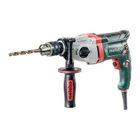
need to know the exact model designation of your
power tool.
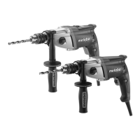
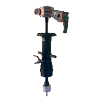
See page 4.
A Angle Drilling and Screwdriving Attachment
B Flexible Shaft
C Drill Stand
D Machine Vice
E Steel-wire End Brush
F Steel-wire Cup Brush
G Steel-wire Wheel Brush
H
Fitting bit spring
For complete range of accessories, see
www.metabo.com or the main catalogue.
Repairs to electrical tools must be carried out by
qualified electricians ONLY!
Any Metabo power tool in need of repair can be
sent to one of the addresses listed in the spare
parts list.
Please enclose a description of the fault with the
power tool.
Metabo's packaging can be 100% recycled.
Scrap power tools and accessories contain large
amounts of valuable resources and plastics that
can be recycled.
These instructions are printed on chlorine-free
bleached paper.
Only for EU countries: Never dispose of
power tools in your household waste! In
accordance with European Guideline
2002/96/EC on used electronic and
electric equipment and its implementation in
national legal systems, used power tools must be
collected separately and handed in for
environmentally compatible recycling.
Explanatory notes on the specifications on page 2.
Changes due to technological progress reserved.
P
1
= Nominal power input
P
2
= Power output
n
0
= No load speed
n
1
= Speed at rated load
ø max = Max. solid drill diameter
b = Chuck capacity
G = Spindle thread
m = Weight without mains cable
D = spindle collar diameter
Vibration total value (vector sum of three
directions) determined in accordance with
EN 60745:
a
h, D
= Vibration emission value
(drilling into metal)
K
h, D
= Unsafe (vibration)
The vibration emission level given in this informa-
tion sheet has been measured in accordance with
a standardised test given in EN 60745 and may be
used to compare one tool with another. It may be
used for a preliminary assessment of exposure.
The declared vibration emission level represents
the main applications of the tool. However if the
tool is used for different applications, with different
accessories or poorly maintained, the vibration
emission may differ. This may significantly
increase the exposure level over the total working
period.
An estimation of the level of exposure to vibration
should also take into account the times when the
tool is switched off or when it is running but not
actually doing the job. This may significantly
reduce the exposure level over the total working
period.
Identify additional safety measures to protect the
operator from the effects of vibration such as:
maintain the tool and the accessories, keep the
hands warm, organisation of work patterns.
9 Tips and Tricks
10 Trouble Shooting
11 Accessories
12 Repairs
13 Environmental Protection
14 Technical Specifications





 To Next Page