9
ENGLISH
• The use of electric coupling devices and
adapters is not permitted during operation.
• The dust-collection container must be
emptied when
necessary, but should
always be emptied after use. Only original
replacement parts should be used.
• Fluids, aggressive gases, e
asily
flammable materials or glowing particles
(glowing embers or similar) should not be
extracted. It is prohibited to use the dust
extractor e.g. in paintshops. Extraction at
wood-processing machines where active
ignition sparks and glowing embers are
expected (e.g. multiple-bladed saws) is
prohibited.
• Do not extract from sources of sparks!
Do
not extract from spark-generating
machines!
• Caution! Clean the machine after it has
been used, bu
t a minimum of once a day!
(See Section 9)
• Mechanisms
All moving machine components driven by
electr
ic motors must be covered by static,
safely attached protective panelling that can
only be removed using tools.
Other risks: If a panel that can only be
disassemble
d using tools is removed, there is
a possibility of injury from the operating
machine.
• Electrics
All electrical components must b
e covered by
static, safely attached protective panelling
that can only be removed using tools. The
machine corresponds to safety class I in
accordance with EN 60 335.
Other risks: If a panel that can only be
disassemble
d using tools is removed, there is
a danger of electric shocks.
• Dust
Using disposable dust bags with
a sealable
opening ensures dust-free disposal of
collected material.
Other risks: When a dust bag is changed,
there is a risk of
inhaling dust.
Compliance with the instructions in Section
10 (Disposing
of collected material) minimises
these dangers.
The machine is already fully assembled.
1) Remove the packaging foil.
2) Unscrew and remove the corner plate
that
secures the machine to the pallet.
3) Lift the machine from the pallet with help
from a second
person.
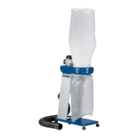
See page 3.
1 Latches (dust containers)
2 Filter housing
3 Cleaning lever
4 Pressure gauge
5 Button (overload protection), only with
SPA 2002 W
6 On/off switch
7 Lockable machine roller
8 Dust containers
9 Viewing window (filling level)
Note: The extraction hose and dust bag
supplied are lo
cated inside the container (8).
7.1 Setting up
The dust extractor should
be set up as close
to the wood-processing machine as possible.
It should be set up on a level surface. Lock
the rear machine roller.
7.2 Inserting the dust bag
1) Fold up both latches (1) simultaneously:
T
he container (8) is lowered.
2) Roll the container forwards.
3) Insert new dust bag in the container
(make sure that the dust bag
rests as
flush against the container wall as
possible) and fold approx. 6-10 cm over
the edge of the container, minimising
creases while doing so (see Figure on
page 3).
4) The dust bag should rest flush in the area
around the
viewing window (9) so that the
filling level can be seen clearly.
5) Roll the container under the dust
extractor.
6) Close both latches (1) : The container is
raised and forms a
tight seal with the dust
extractor.
The next time the machine is switched on, a
vacuum
is generated in the container. The
dust bag then automatically nestles against
the wall of the container, optimising use of the
dust bag capacity.
7.3 Connecting the extractor hose
Only use electroconductive hoses.
Hoses made from plastic must be
flame-retardan
t.
1)At one end of the spiral hose,
strip the me
tal spiral so that approx. 5 cm
of the metal spiral protrudes.
2) Cut off the piece of hose that the metal
spi
ral was removed from.
3) Bend the stripped piece of metal spiral in
such a way that it protrudes inside the
spiral hose
.
4) Push the end of the hose (and one hose
clamp
) over the extractor connection
piece from the dust extractor and secure
with the hose clamp: Attach the hose
clamp in such a way that the stripped
metal spiral is pressed against the
extractor connection piece on the dust
extractor to ensure that there is an
electroconductive connection.
Make sure that the electrical
connection between the hose and
extractor
connection piece on the
dust extractor is perfect.
7.4 Power supply
Before plugging in check to see that
the rated mains voltage and mains
fre
quency, as stated on the rating
label, match with your power
supply.
When connecting the three-phase
version (SPA 2002 D), pay
attent
ion to the correct rotational
direction.
7.5 Switching On and Off
After connecting the extraction hose to the
wood-processing machine:
1) first switch on the dust extractor at the on/
off switch (
6),
2) then switch on the wood-processing
machine
Perform these actions in reverse order w
hen
switching off the machines.
The vacuum should be monitored at the
pressure ga
uge (4).
a.) Use as a dust extractor
Wood-processing machines with differen
t
extraction connection piece diameters can be
connected to the dust extractor. Pay attention
here that the extracted volumetric flow does
not fall below the minimum quantity. This
minimum volumetric flow depends on the
diameter of the connection piece on the
machine generating the dust.
There are red areas on the pressure gauge
scale, which are marke
d with the extractor
connection piece diameters.
If the pointer of the pressure
gauge is in the red area of the
extr
actor connection piece being
used, the filter must be cleaned.
Note: The minimum volumetric flow on the
dust extractor is monitored by measuring the
vacuum
upstream of the ventilator. If the
maximum permitted vacuum value is
exceeded, the pointer moves to the red area.
If the diameter of the extractor connection
piece o
r minimum volumetric flow at the
machine generating dust is between the
range of values in the table, the next largest
diameter is used for monitoring the value.
The ratios are shown in the following table:
Meaning of columns:
Column 1: Diameter of extractor connection
piece o
n the wood-processing machine.
Column 2: Minimum volumetric flow in
extractor connection piece a
t 20 m/s.
Column 3: Possible vacuum at start of
extractio
n hose (2.5 m long). Interface
between machine generating dust and dust
extractor, at minimum volumetric flow. The
manufacturer of the wood-processing
machine specifies the vacuum required for
the machine. This value must be less than the
value for the dust extractor in order for
extraction from the wood-processing machine
to occur as specified.
Column 4: Vacuum indicated on the pressure
gauge scale.
1234
(mm) (m
3
/h) (Pa) (Pa)
100 565 1020 1560
80 362 1460 1740
63 224 1680 1840
b.) Use as a vacuum cleaner
With the cleaning nozzle, order no.
0913031270, the dust extractor can also be
used as a va
cuum cleaner for vacuuming
deposited wood dust or chips, and
corresponds to applicable regulations, even
for oak and beech wood dust.
Here, the minimum volume flow is also
monitored a
t the pressure gauge. For a
cleaning nozzle with a connector diameter of
100 mm, the filter must be dedusted if the
pointer on the pressure gauge is in the red
area of the 100 mm extractor connection
piece diameter being used.
If the pointer of the pressure gauge is in the
red
area, the filter must be cleaned.
Clean the machine after it has been used, the
filter sho
uld be dedusted a minimum of once
a day!
1) Switch off the wood-processing machine
4 Preventing danger
5 Delivery and assembly
6 Overview
7 Initial Operation 8 Monitoring the minimum volume flow
rate
9 Dedusting the filter
 Loading...