20 Control Modules—Network Control Module 200 Series
This section starts by illustrating the N1 LAN connections for new and
retrofit applications. N2 cabling to the communications terminal board is
described in the Network Control Unit/Network Expansion Unit Technical
Bulletin (LIT-636020), and the N2 Communications Bus Technical
Bulletin (LIT-636018).
This section then organizes cable connections by device (such as by OWS,
printer, etc.) and finally by migration type (Gateway or S2). Devices
connecting to both the RS-232 submodule and the integrated RS-232 port
show two cables, since the pinouts for those connections are different.
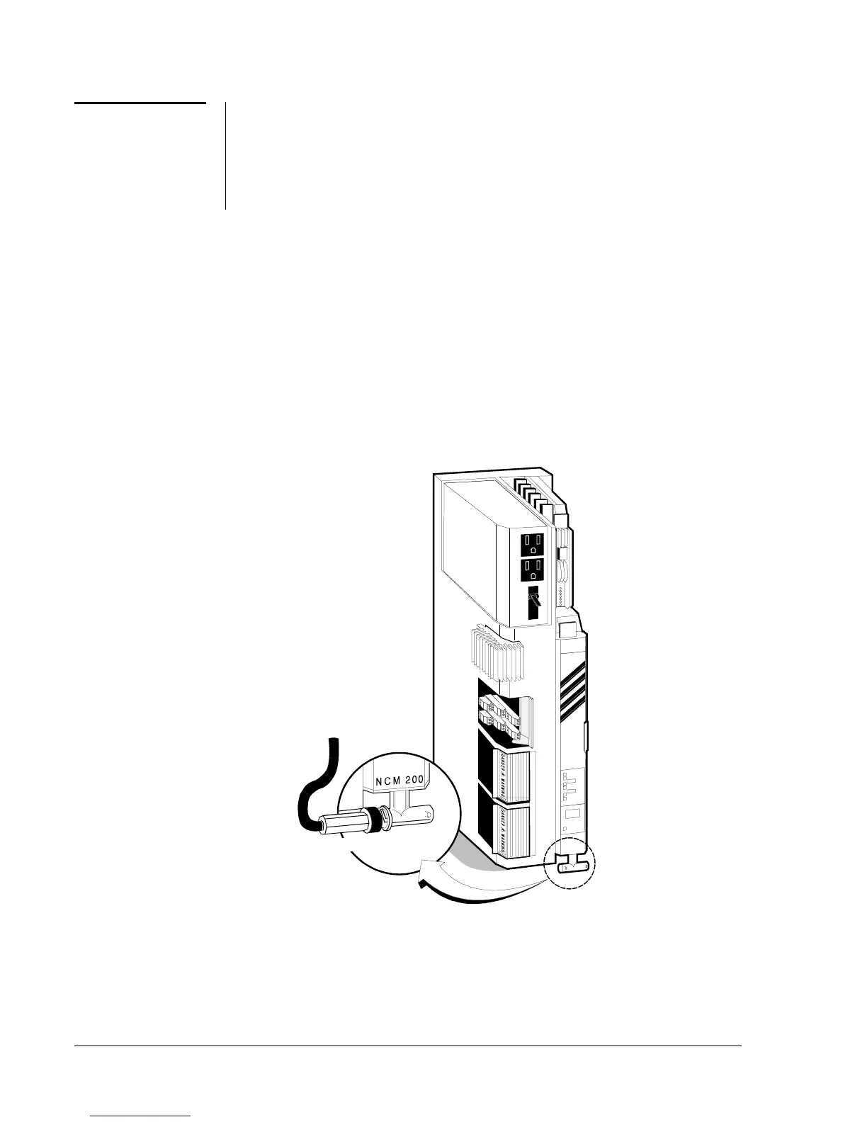
Using the NCM-Only Base Frame
Connect the N1 cable via a T-connector to the bottom of the NCM200
module, as shown in Figure 6. Ensure that no metal part of the connection
(EOL cap, T-connector, or exposed metal part of the cable) is touching a
case or any metal on the base frame. Black tape, or a clip-on plastic
shroud, will protect the metal from inadvertent contact.
Power Supply
NCM200
TC200_6
N1 LAN Connection
Add terminal cap or
continue N1 LAN at
left side of "T."
Apply black tape or
plastic shroud around
metal connections.
1.
2.
Figure 6: Making N1 LAN Connections Using
NCM-Only Base Frame
NCM Cable
Guidelines
NCM200 N1 LAN
Connection
 Loading...