Control Modules—Network Control Module 200 Series 21
Using Standard Base Frames
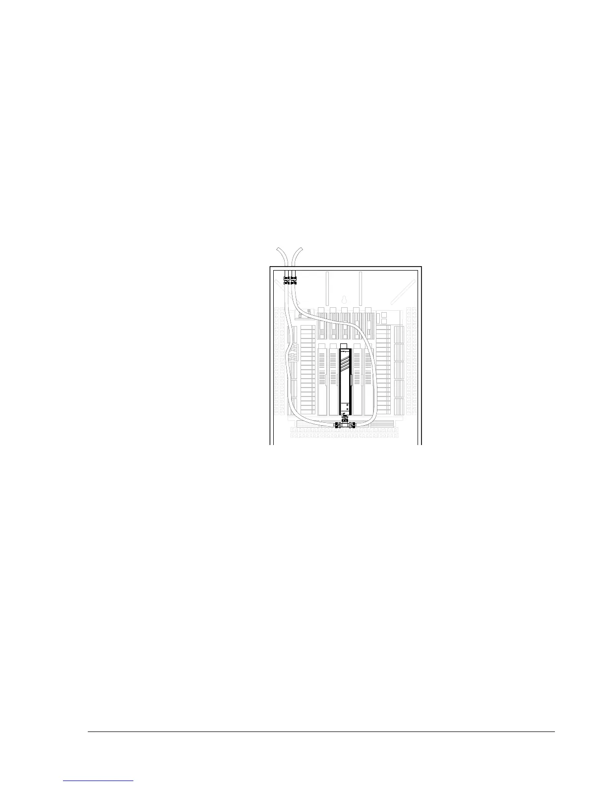
Figure 7 illustrates the method of connecting the N1 LAN to the NCM200
in applications that install the NCM200 in a standard 1-slot, 2-slot, or
5-slot base frame (e.g., a retrofit application). Remove the incoming and
outgoing N1 cables from the TBC. Attach a female barrel connector to
each cable end. Then add an extension cable from the incoming N1 cable
to a T-connector at the bottom of the NCM200 module. Add a second
extension cable backup to the outgoing N1 cable (if a terminator cap is
used, cap the outgoing side of the T-connector). The extension cable must
be the same type as the main N1 cable. Apply the same precautions for
inadvertent metal contact as described for Figure 6.
N2 BUS
DIAGNOSTIC
5-slot Base Frame
with NCM200 Installed
N1 cables
connect to
extension
cables, not
the TBC.
TC200_7
Extension cables
must
be the same
type used
by the main N1 cable.
Figure 7: Method to Make NCM200 N1 LAN Connections
Using Standard Base Frames
 Loading...