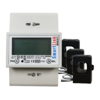
The MOD3CT is a three-phase kWh Modbus energy meter designed for accurate measurement and monitoring of electrical consumption. Housed in a compact 4-module (60mm) casing, it features an LCD display and boasts a high accuracy class (Class 1). This meter is built to DIN, IEN, and EN standards, ensuring excellent long-term stability and comes with a 1-year warranty. It holds MID B approval, making it suitable for both business and invoicing purposes in accordance with European and International standards. The MOD3CT can handle connection rates of up to 950A.
Key Technical Specifications:
- Nominal Voltage (Un): 230/400V AC (3~)
- Operational Voltage: 161/279 - 300/520V AC (3~)
- AC Voltage Withstand: 4KV for 1 minute
- Impulse Voltage Withstand: 6KV - 1.2 µS waveform
- Basic Current (Ib): 1.5/10A
- Max. (Imax): 6/100A
- Starting Current (Ist): 0.4% of Ib
- Imin | Itr: 5%lb | 10% lb
- Over Current Withstand: 30Imax for 0.01s
- Operational Frequency Range: 50Hz ±10% | 60Hz ±10%
- Internal Power Consumption: ≤2W /10VA per phase
- Power Consumption on Current Circuit: ≤ 4VA
- Test Output Flash Rate (PULSE LED): 400, 800, 1600 or 3200imp/kWh
- Test Pulse Output Rate (pins 8 & 9): 400, 800, 1600 or 3200imp/kWh
- CT Changing Ratio: 27 ratios to choose
- Accuracy Class: 1/B (Active Energy), 2 (Reactive Energy)
- Protection Against Penetration of Dust and Water: IP51
- Insulating Encased Meter of Protective Class: II
- Mechanical and Electromagnetic Environmental Classes: B
- Dimensions (Width x Height x Depth): 17.5 x 112 x 60 mm
- Weight: 0.4kg (net)
Accuracy (with balanced loads):
- Voltage, LN & LL (Phase 1,2,3): ±0.5%
- Amps (Phase 1,2,3): ±0.5%
- PF (Phase 1,2,3 & Σ): ±0.2%
- Active Power (Phase 1,2,3 & Σ): ±0.5%
- Reactive Power (Phase 1,2,3 & Σ): ±0.5%
- Apparent Power (Phase 1,2,3 & Σ): ±0.5%
- Frequency: ±0.2%
- Active Energy: ±1%
- Reactive Energy: ±1%
Modbus Communication Specifications:
- Bus Type: RS485
- Protocol: MODBUS RTU with 16bit CRC
- Baud Rate: 1200, 2400 (default), 4800, 9600
- Address Range: 1-255 user settable (64 meters per Bus)
- Range: 1000m
Usage Features:
The MOD3CT features an LCD display that shows L1, L2, L3 voltage and current. A red LED flashes to indicate pulse output, with faster flashing indicating higher energy consumption. The LCD numerical display shows 8 digits (6 + 2) for main readings and 6 digits for sub-display items. It includes indicators for RS485 communication, phase failure (negative or OV), and a pulse output indicator.
Meter Reading and Navigation:
The meter displays accumulated energy (auto-scroll only) and allows for auto or manual scrolling through V/I/P/PF/Hz/Comms data. A "Config / Change Button" (PRG) and a "Scroll / Select Button" (SEL) are used for navigation and configuration. A full-screen display will last for 3 seconds. The meter also displays a constant value and the software version.
- Right button (SEL): Used for selection.
- Left button (PRG): Used for programming.
- Short press of SEL: Lights the backlight and cycles through parameters: voltage of one phase, current of one phase, active power, reactive power, frequency, baud rate, ID address, serial number (total 13 parameters). The backlight automatically closes after one minute.
- Long press of PRG (more than 3 seconds): Enters code confirmation process. Use SEL to choose the code number, then PRG to change the digit place. After entering the code, long press PRG to confirm. The display will show "ID 01". Use PRG to change the display item and SEL to change the information.
- Settable items: ID, baud rate, number of display items (Phase voltage, phase current, active power, reactive power, frequency, communication baud rate, ID address, serial number), and CT ratio setting.
CT Ratio Setting:
The CT ratio can be set to 27 different ratios (1, 2, 5, 8, 10, 12, 15, 16, 20, 24, 30, 40, 50, 60, 70, 80, 90, 100, 110, 120, 130, 140, 150, 160, 170, 180, 190).
To set the CT ratio:
- Press and hold PRG for 5 seconds.
- Press SEL once and select "1" (password 0001).
- Press and hold PRG for 5 seconds. The ID button will display.
- Press SEL to set the CT ratios.
- After setting, press and hold PRG for 5 seconds. "YES" will display to confirm settings are programmed.
To check the CT ratio, turn the meter off and on again; the 4th screen will display the set ratio (e.g., "5--500" for a CT ratio of 100).
Quick Programming Guide:
- Connect mains power: Live to terminal 27 (lower left), Neutral to terminal N (upper right).
- Switch on power and wait for startup (CT ratio display).
- Press and hold PRG for 3 seconds ("PS 0000" displays).
- Press SEL once ("PS 0001" displays).
- Press and hold PRG for 3 seconds to enter password (default 0001).
- The meter is now in programming mode.
- "Id" (Modbus address): 2-digit hexadecimal. Use SEL to increment, PRG to move to next item.
- "bd" (Modbus baud rate): 5 values (0600, 1200, 2400, 4800, 9600). Use SEL to increment, PRG to move to next item.
- "Sn" (Number of parameters to show): 2-digit hexadecimal. Default "0E", max settable "0d". Use SEL to increment, PRG to move to next item.
- "Cr" (CT ratio): Multiplied by 5 for current rating. 27 possible values. Use SEL to increment.
- Press and hold PRG for 3 seconds to save. "YES" confirms saving.
Installation:
- Connecting wires should be sized according to local codes and regulations for the circuit breaker or overcurrent device.
- An external switch or circuit-breaker, acting as a disconnection device, should be installed on the inlet wire, close to the meter for operator convenience.
- An external fuse or thermal cut-off for over-current protection must be installed on the supply side wire, close to the meter.
- The meter can be installed indoors directly or in a waterproof meter box outdoors, adhering to local codes.
- Secure the meter with a padlock to prevent tampering.
- Install against a fire-resistant wall in a well-ventilated, dry place.
- In dangerous or dusty environments, install in a protection box.
- The meter can be installed on a 35mm DIN rail.
- Install at an accessible height for easy reading.
- Use Surge Protection Devices in areas with frequent surges (e.g., thunderstorms, welding machines).
- After installation, seal the meter to prevent tampering.
Wiring Connections:
- 30: Reactive pulse output contact active (-)
- 31: Reactive pulse output contact active (+)
- 32: Active pulse output contact (-)
- 33: Active pulse output contact (+)
- 34: RS485 B (Modbus)
- 35: RS485 A (Modbus)
- L1: L1 phase wire
- L2: L2 phase wire
- L3: L3 phase wire
- N: Neutral wire
Modbus Cable Type:
Use a shielded twisted pair (telephone type), AWG18 cable or equivalent. The twisted pair design improves immunity to electromagnetic disturbances. All 'A' terminals must be connected together, and all 'B' terminals must be connected together. Incorrect A/B connections can prevent communication and disrupt the entire system. Use consistent cable colors for A and B terminals to avoid errors.
Maintenance Features (Troubleshooting):
- Power supply indicators off: Check power source connection, L1/L2/L3/N connections, 230V/400V AC voltage, fuses, and surge protection.
- Register doesn't count: Check for load connection (P- or P+ LED flashing), 40 flashes of LED at 400 pulses/kWh equals 0.1kWh.
- No pulse outputs: Check DC power supply (5-27V DC), correct connection of collector (pin 28+ or 30+) and emitter (pin 29- or 31-) connections.
- Pulse output rate incorrect: Contact technical support.
- Consumption LED not flashing: Check pulse cable connection, load on the line (Ohm meter readings).
- No data received by Modbus: Check Meter ID (A in display, default 0A), communication distance (max 1000m), number of meters (max 64), and Modbus terminal connections (34 and 35).
The MOD3CT Series DIN rail energy meter is equipped with a pulse output, fully separated from the internal circuit, which generates pulses proportional to the measured energy for accuracy testing. This output is used for recording consumption and cannot be reset to zero. The reading accuracy is 1/100 kWh.