Doc# 1231558 • REV C (November 2017) Page 13 of 20
CAUTION: The default setpoint as shipped from the factory is
not intended to be suitable for any parcular machinery appli-
caon. Each applicaon requires that the setpoint be careful-
ly eld adjusted for the specics of your machine as outlined in Secon
4.2 below. Failure to adjust the setpoint in this manner constutes a
misuse of the product and may lead to ineecve machinery protecon
resulng in extensive machinery damage and personnel injury.
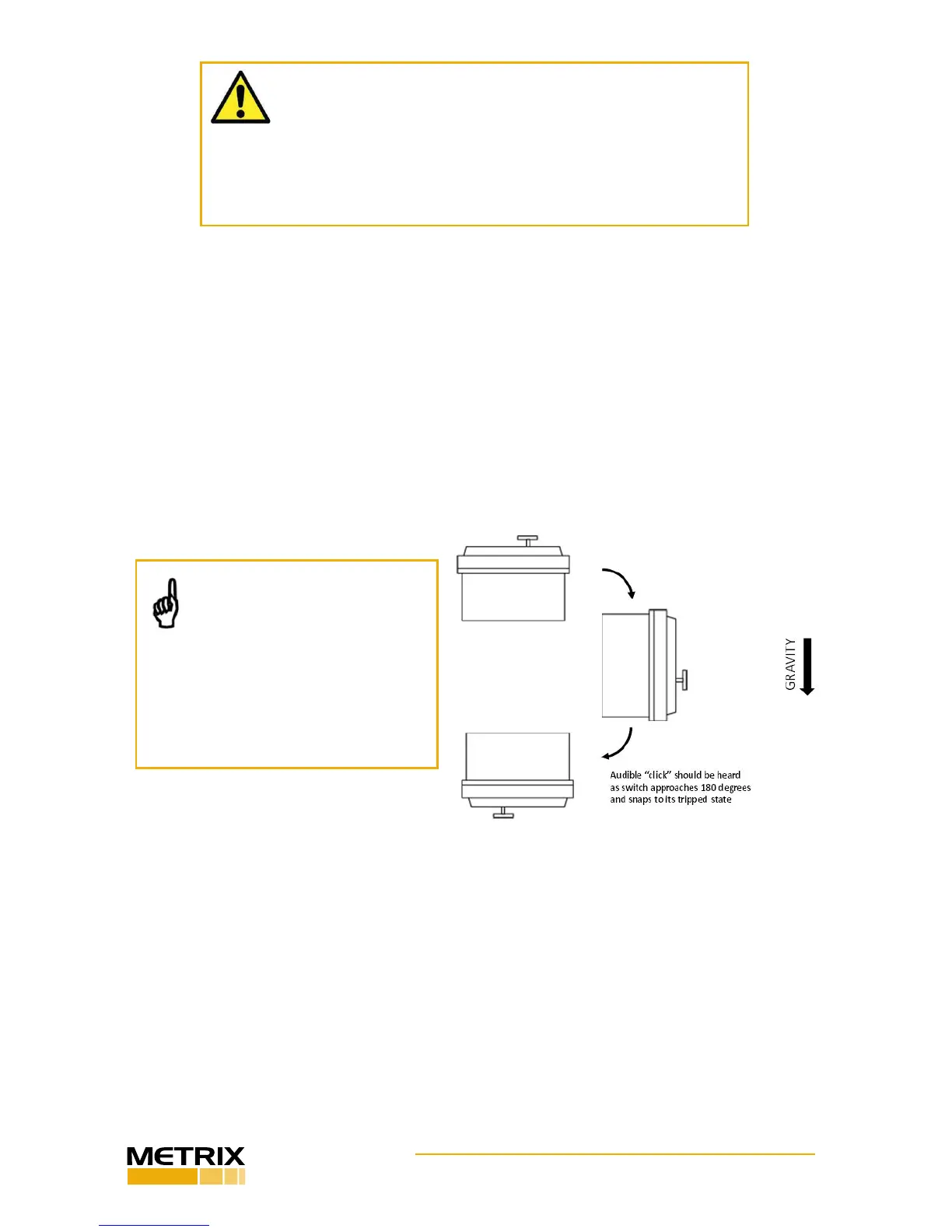
up and rotate it to an upside down posion as shown in Figure 12. As the switch reaches
the 180-degree posion, you should hear an audible “click” indicang it has snapped to its
tripped state. If the device does not trip, turn the setpoint adjustment screw approximately
1/16th turn CCW and repeat the above procedure. Connue adjusng in 1/16th CCW turn
increments unl the unit trips when turned from right side up to upside down. When per-
forming this vericaon on the Model 5550G, it is recommended that you leave the cover
o. The presence or absence of the cover does not aect the setpoint during the vericaon
process and ensures the cover does not have to be repeatedly removed and reinstalled to
adjust the setpoint and reset the trip plate. However, never remove the cover with ener-
gized wiring connected – remove power before opening cover.
NOTE: If the switch will not
reset, adjust the setpoint screw
1/8th turn CW and press the
reset buon. Repeat this pro-
cedure, adjusng 1/8th of a turn each
me, unl the device can be reset.
While performing this procedure,
keep the device sing on a at sur-
face with the cover side facing up.
4.2 In-Situ Setpoint Adjustment
The setpoint adjustment is accessible externally on the model 5550 (see Figure 3). For model
5550G, the lid must be removed. Follow the steps below to adjust the setpoint for the par-
culars of your machine.
4.2.1 Verify the factory setpoint as described in 4.1 above. Then, rotate the adjustment
screw one full turn (360 degrees) clockwise and proceed to step 4.2.2.
4.2.2 Install the switch on the machine following the guidelines of secon 3. Ensure
the eld wiring is disconnected. If it has already been connected, disconnect temporarily,
Figure 12: Verifying the factory default
setpoint on the 5550
 Loading...
