Doc# 1231558 • REV C (November 2017) Page 8 of 20
2.7 Mounng Rotaon
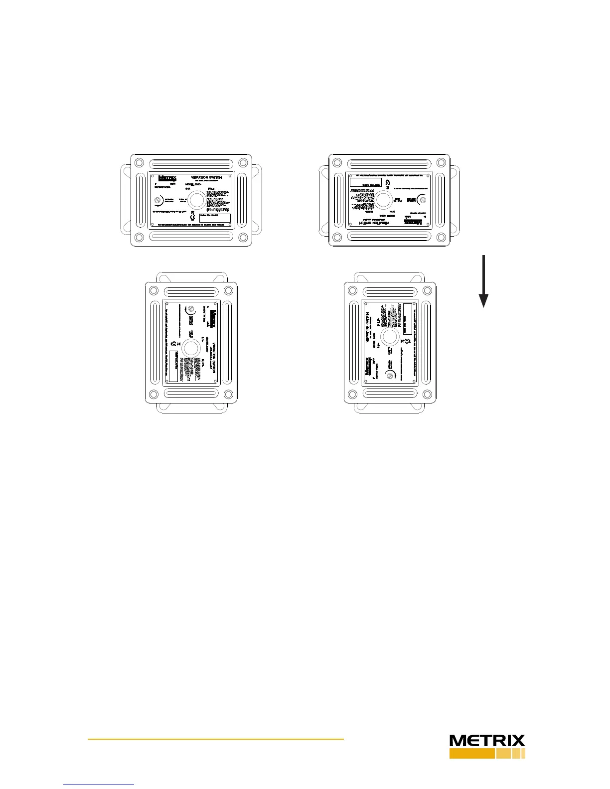
The switch can be rotated about its sensive axis without aecng its operaon (Figure 9).
Thus, posions 9A, 9B, 9C, and 9D showing the model 5550 switch rotated at 12:00, 3:00,
6:00, and 9:00 posions respecvely do not aect the operaon of the switch and are pri-
marily a maer of preference and serviceability. However, when possible, it is recommend-
ed that conduit ngs be oriented facing down, helping to prevent moisture or condensa-
on accumulaon inside the device.
2.8 Axing The Switch To The Machine
Mount the switch securely to the machine using the 4-hole paern (5550) or 2-hole paern
(5550G) on the baseplate. It is extremely important that the device be rigidly aached
to the machine so that it reects machinery vibraon – not vibraon incurred by a loose
mounng, an insuciently s mounng bracket, or a bracket resonance. Also, the switch
should be mounted in a locaon where its own mass does not appreciably aect the natural
frequency(ies) of the member to which it is aached. When aaching to a support beam,
skid, or other member, thought should be given to the usefulness of the measurement and
what level of machinery damage must be present before sucient acceleraon will occur at
the measurement locaon. For addional applicaon assistance, consult the factory or your
nearest Metrix representave.
2.9 Wiring
The switch provides a single SPDT relay or oponal double SPDT relays, allowing use as a
DPDT device. When a reset / startup delay coil is specied (oponal on 5550; standard on
5550G), suitable wiring terminals are also available. Refer to Figure 10 for wiring terminal
assignments.
9A - 12:00 horizontal orientaon
9B - 3:00 horizontal orientaon
9C - 6:00 horizontal orientaon
9D - 9:00 horizontal orientaon (preferred)
Figure 9: Horizontal orientaons of 5550. 9D posion is strongly recommended
(conduit hole facing down) to allow drainage oof any accumulated condensaon.
GRAVITY