Doc# 1231558 • REV C (November 2017) Page 9 of 20
When wiring the device, observe the following:
2.9.1 Do not exceed switch contact rangs listed on the nameplate.
2.9.2 Comply with all applicable electrical codes.
2.9.3 Keep eld wiring away from the moving parts of the trip plate mechanism.
2.9.4 All power must be switched o before opening the enclosure in an explosive
atmosphere.
2.9.5 The switch must be electrically connected by means of a ameproof/dust cable
gland or stopping box cered to IEC60079-0:2011 (EN60079-0:2012), IEC60079-1:2007
(EN60079-1:2007), and IEC600079-31:2008 (EN60079-31:2009).
2.9.6 For ambient temperatures below -10°C, use eld
wiring suitable for the minimum ambient temperature.
2.9.7 Reinstall the cover by rst ensuring the o-ring
is in place and properly seated in the housing’s groove.
Place the cover on the unit and screw ght (model
5550G) or by torqueing the four cover bolts shown in
Figure 11 (model 5550 only) to 6-7 /lbs.
NOTE: It is not recommended
that wiring be connected to the
device unl aer verifying the
factory default setpoint in Secon
4.1 and performing the in-situ setpoint
adjustments in Secon 4.2. This will pre-
vent having to disconnect the wiring and
remove the device from its mounng loca-
on. It will also prevent unwanted trips
while inially adjusng the setpoint.
WARNING: Voltages present at
switch terminals can result in
serious injury or death. Always
de-energize these circuits prior
to installaon or maintenance and use
appropriate lock-out / tag-out proce-
dures where applicable.
CAUTION: If eld wiring is allowed to obstruct the
moving parts of the switch, it may prevent the trip
plate from operang correctly. Machinery protec-
on can be compromised and serious machinery damage
and/or personnel injury may result.
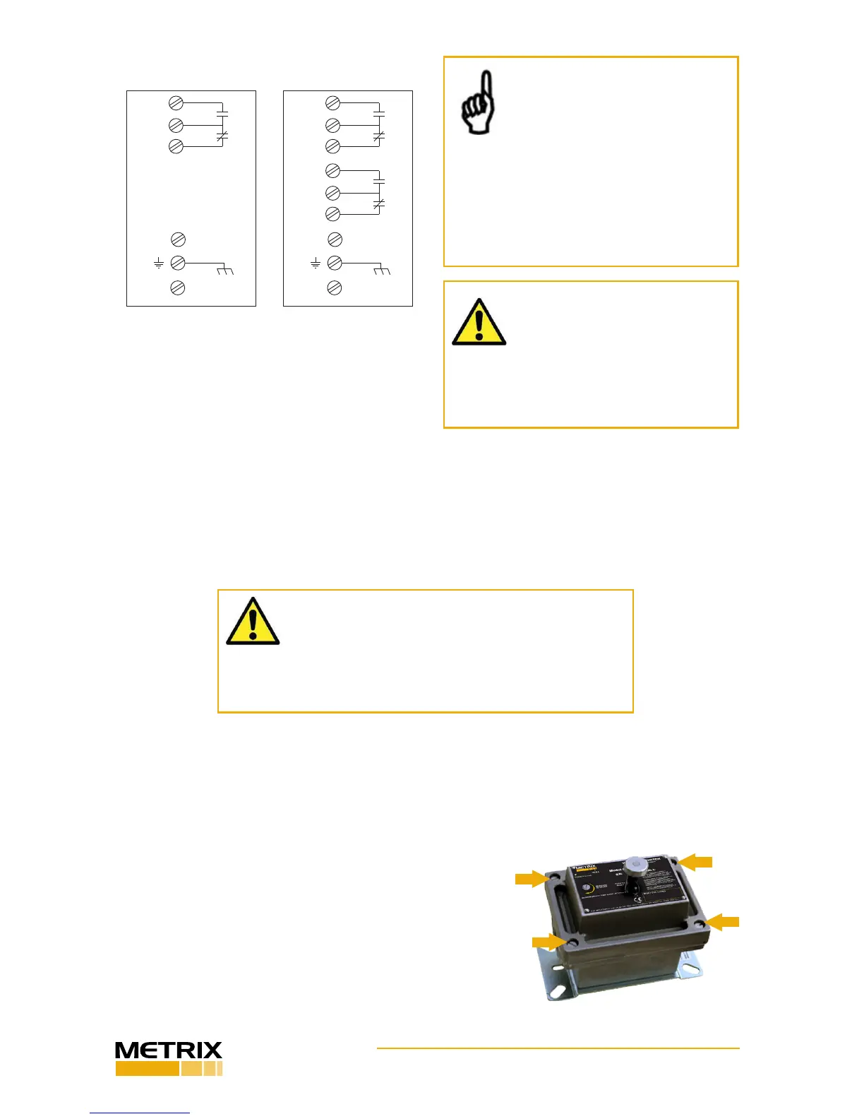
NOM
OPEN
COM
NOM
CLOSED
RESET COIL
CASE
RESET COIL
L(+)
N(-)
GRN
NOM
OPEN
COM
NOM
CLOSED
RESET COIL
CASE
RESET COIL
L(+)
N(-)
GRN
NOM
OPEN
COM
NOM
CLOSED
WIRING DIAGRAM
SPDT DPDT
DPDT CONTACTS AND RESET COIL OPTION
Figure 10: Wiring connecons
Figure 11: 5550 cover bolts locaon
2
1
3
4