Doc# 100545 • REV C (May 2016) Page 3 of 16
RECEIVING, INSPECTING AND HANDLING THE SYSTEM
Metrix ships the probe, extension cable, and driver as separate units that the user intercon-
nects at the installaon site. Carefully remove all equipment from the shipping containers
and inspect it for shipping damage. If you see shipping damage, le a claim with the carrier
and submit a copy to Metrix Instrument Co. Include part numbers and serial numbers on all
correspondence. If no damage is apparent and the equipment is not going to be used imme-
diately, return the equipment to the shipping containers and reseal unl ready for use. Store
the equipment in an environment that is free from potenally damaging condions such as
extreme temperature, excessive humidity, or a corrosive atmosphere.
OVERVIEW
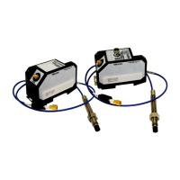
The Metrix Digital Proximity System comes in two versions:
• MX2033 – 3-wire proximity driver
• MX2034 – 2-wire, loop-powered proximity transmier
The followings secons cover each of these in more detail.
MX2033 Three-Wire Proximity Driver
The MX2033 signal output is compable with industry-standard connuous-vibraon moni-
toring systems and is the format specied in API Standard 670. It uses -24VDC excitaon
and provides the output signal in mV/mm, typically 7.87 mV/mm (200mV/mil) for 5 mm and
8mm probes and 3.94 mV/mm (100 mV/mil) for 11 mm probes.
MX2034 Two-Wire Vibraon / Posion / Speed Transmier
The MX2034 signal format is for use when vibraon, axial posion, or rotaonal speed
measurements will be directly connected to a PLC, DCS, SCADA system, or other instrumen-
taon that accepts an ISA standard 4-20 mA signal, without the use of a separate monitor
system. It is powered by +24 VDC, supplied within the current loop. The device is user-pro-
grammable to funcon as either a radial vibraon transmier (where the 4-20 mA signal is
proporonal to peak-peak vibraon amplitude), as an axial posion transmier (where the
4-20 mA signal is proporonal to average probe gap) or as a rotaonal speed transmier
(where the 4-20mA signal is proporonal to sha speed). For convenience when connecng
to signal analyzers, portable data collectors, and test instrumentaon, the raw vibraon /
speed signal is available at a short-circuit protected BNC connector.
INSTALLATION
Probe Installaon
Mount the probe in a simple bracket, such as the Metrix Model 7646, in a tapped hole in
the bearing cap or by means of a Metrix Model 5499 Probe Housing. The laer arrangement
provides an easy means to adjust the probe air gap, especially where the target is some
distance from the outside surface of the machine.
When inserng the probe through the machine case or bearing cap, the signal voltage may
vary widely before the proper gap is obtained. Therefore, be sure the gap is within 0.07” (1.8
mm) of the target before aempng to set the gap electrically. If possible, set the probe gap
while the machine is shutdown, to avoid the danger of damaging the probe in the event that
it touches the sha.
 Loading...