Doc# 100545 • REV C (May 2016) Page 4 of 16
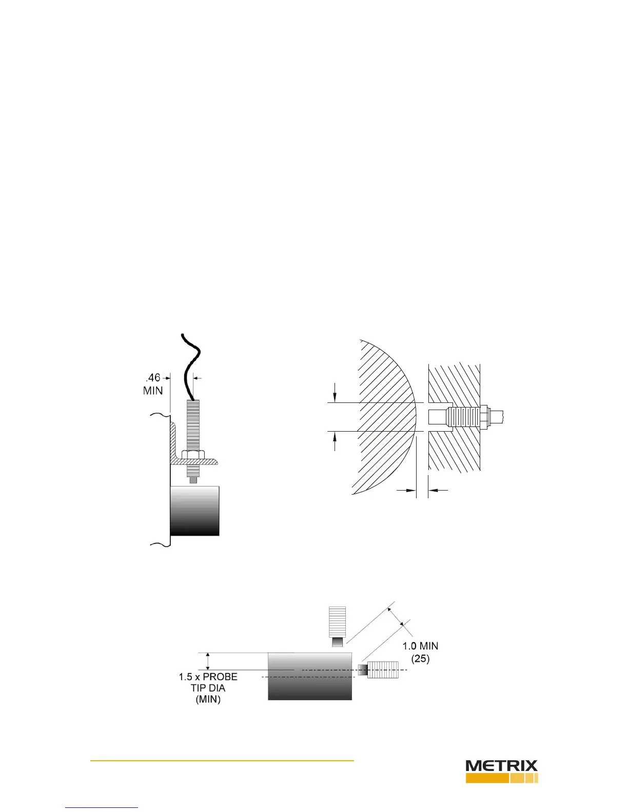
Figure 1: Clearance dimensions for standard 5mm and 8mm radial vibraon measurements.
(Tight View can be closer)
Figure 2: Minimum distance between probe ps.
(Tight View can be closer)
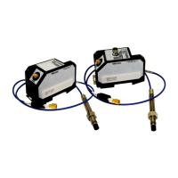
Connect the probe to the driver/transmier using the proper coax extension cable. If a con-
nector must be replaced, the overall length of the probe or extension cable can be reduced
by 2” total without adversely aecng the calibraon and linearity. Insulate the probe con-
nector/extension cable connector juncon with the Metrix 8973 connector insulator.
Radial vibraon measurements
For radial vibraon measurements, mount the probe perpendicular to the sha with the
probe p approximately 0.050” (1.25 mm) from the sha surface. Provide the probe p with
sucient clearance from surrounding metal to prevent an erroneous output. As a minimum,
the clearance diameter should be 0.75” (19 mm) for the full length of the probe p. See
Figure 1. You can set the probe gap “electrically” to the center of its measurement range by
observing the DC output voltage at the BNC connector on the MX2034 or the terminal block
connecon on the MX2032 / MX2033 with an isolated meter. Adjust the probe gap to obtain
-10 VDC, which corresponds to a gap of approximately 0.050” (1.25 mm). The preferred
stac gap range is 0.035” to 0.050”. This gap corresponds to a voltage of -7.0 VDC to -10
VDC. To prevent cross-feed between two probes mounted in the same vicinity, maintain a
minimum 1.0” (25 mm) spacing between the probe ps. See Figure 2.
0.75” (19 mm)
MIN
GAP