Doc# 100545 • REV C (May 2016) Page 5 of 16
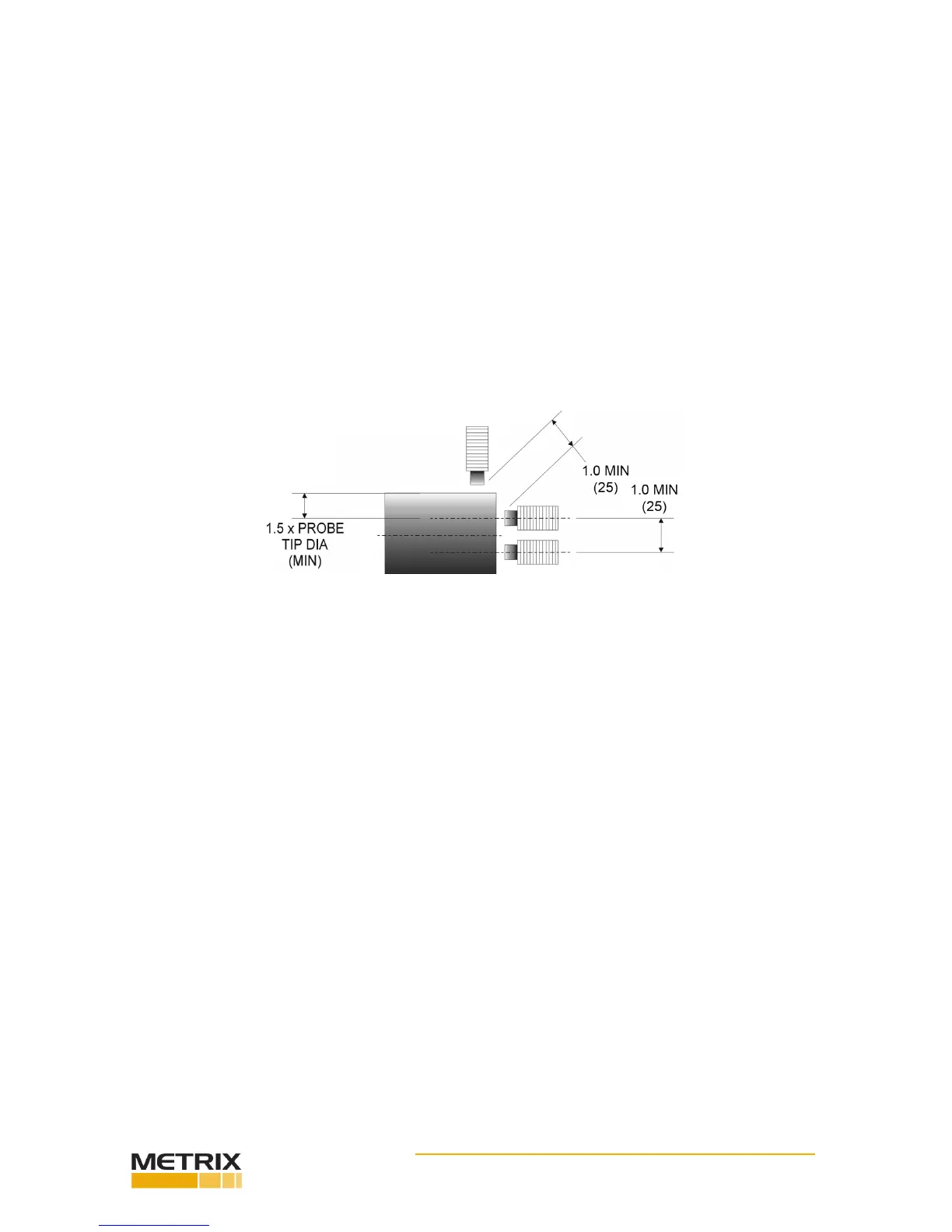
Figure 3: Key dimensions for thrust measurements
Thrust measurements
For thrust measurements ensure the thrust range is within the probe range. Move the ma-
chine to ensure the thrust range is set properly within the probe linear range.
For posion (thrust) measurements, mount the probe with the probe axis parallel to the
sha and with the probe p approximately 0.050” (1.25 mm) from the end of the sha. For
11 mm diameter probes, this distance is approximately 0.088”(22mm). Provide the probe p
with sucient clearance from surrounding metal to prevent an erroneous output. As a mini-
mum, the clearance diameter should be 0.75” (19 mm) for the full length of the probe p.
For an 11mm probe, the minimum clearance should be 0.88” (22 mm). See Figure 1. You
can set the probe gap “electrically” to the center of its measurement range by observing the
DC output voltage at the BNC connector with an isolated meter. Adjust the probe gap to ob-
tain -10 VDC, which corresponds to a gap of approximately 0.050” (1.25 mm). The preferred
stac gap range is 0.035” to 0.050”(0.8 to 1.25 mm). This corresponds to a gap voltage of
-7.0 VDC to -10 VDC. Note that for 11 mm probes, the voltage is -9 VDC. To prevent cross-
feed between two probes mounted in the same vicinity, maintain a minimum of 1.0” (25
mm) spacing between the probe ps. For 11 mm probes, this distance is approximately 1.5”
(38mm). See Figure 3.
Speed measurements
For RPM measurements, mount the probe with its axis radial to the sha with its p approxi-
mately 0.050” (1.25 mm) from the outermost surface of the sha. The probe p must be
provided with sucient clearance from surrounding metal to prevent an erroneous output.
As a minimum, the clearance diameter should be 0.75” (19 mm) for the full length of the
probe p. See Figure 4. For the exact gapping procedure, see the secon concerning calibra-
on. To prevent cross-feed between two probes mounted in the same vicinity, at least 1.0”
(25 mm) spacing between the probe ps should be maintained. See Figures 5, 6.
The minimum keyway depth is 0.060” (1.5 mm). The minimum keyway width and key width
is the diameter of the probe p (Figure 7). These minimums will ensure that the transmit-
ter or driver responds properly to the keyway at all RPMs. Some experimentaon may be
required such as adjusng the probe gap or modifying the keyway dimensions.
The probe can be mounted in a simple bracket, such as the Metrix Model 7646, in a tapped
hole in the bearing cap or by means of a Metrix Model 5497PM or 5499 Probe Housing. The
laer arrangement provides an easy way to adjust the probe air gap, especially where the
target is some distance from the outside surface of the machine.