Doc# 100545 • REV C (May 2016) Page 6 of 16
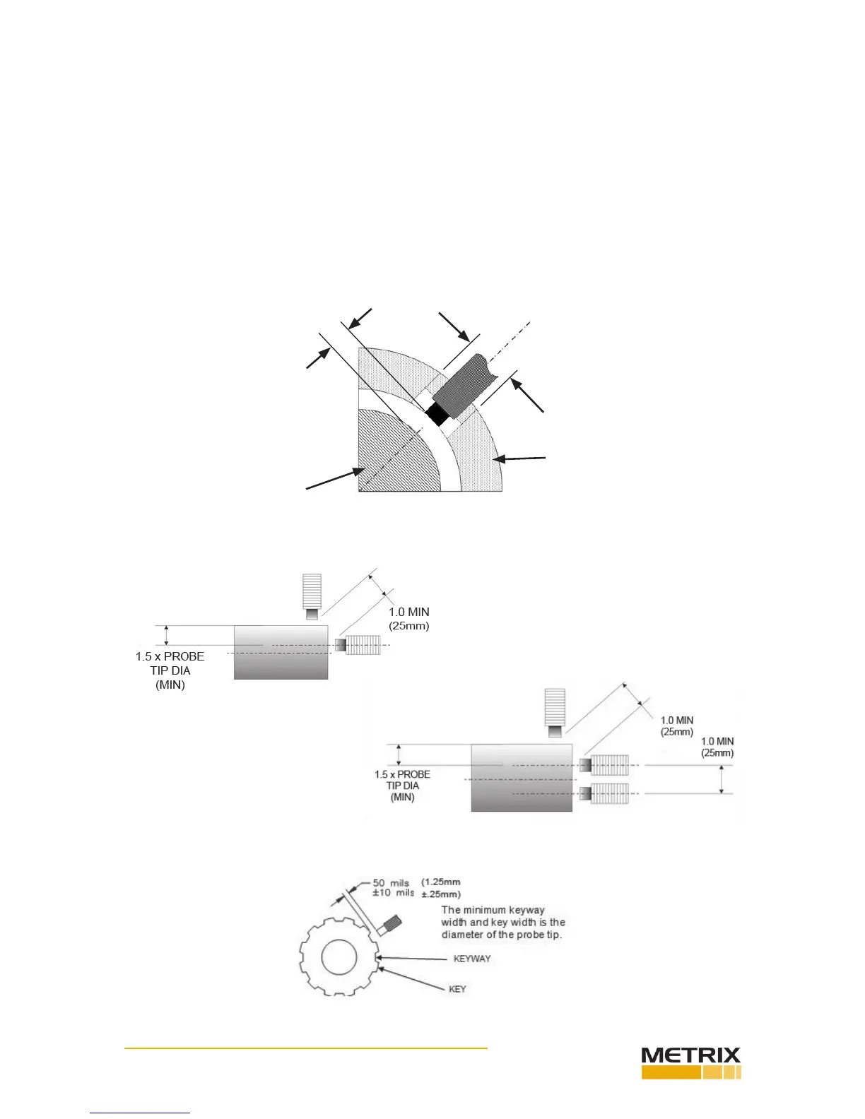
Figure 4
Figure 5
Figure 6
When inserng the probe through the machine case or bearing cap, the signal voltage may
vary widely before the proper gap is obtained. Therefore, be sure the gap is within 0.07” (1.8
mm) of the target before aempng to set the gap electrically. If possible, set the probe gap
while the machine is shutdown, to avoid the danger of damaging the probe in the event that
it touches the sha.
Connect the probe to the transmier using the proper extension cable such that the com-
bined system length of probe + cable matches the transmier conguraon (refer to Metrix
datasheet 1028003, ordering opon B). Do not change the length of the extension cable
from the system, as such acon will adversely aect the calibraon and linearity. If a con-
nector must be replaced, the overall length of the cable can be reduced by 2” without harm.
Insulate the probe connector / extension cable connector juncon with the Metrix Model
8973 connector insulator.
Figure 7
HOUSING
0.75” (19mm)
Min Clearance
SHAFT
GAP
 Loading...