Doc# 100545 • REV C (May 2016) Page 7 of 16
Extension Cable Installaon
Route the extension cable using the following guidelines:
• Check that the Driver/Transmier, extension cable, and probe belong to the same system
(e.g. Metrix 10000 Series or Metrix 3300 series) and that the total system length is cor-
rect (5m or 9m).
• Secure the extension cable to supporng surfaces or places in conduit. Make certain the
cable is not kinked, scraped, nor bent beyond the minimum recommended radius of 1”.
• Secure coaxial connectors between the extension cable and the proximity probe. Con-
necon should be “nger ght” with an addional quarter turn using an open ended
9/32” wrench or equivalent.
• Insulate the connecon between the probe lead and the extension cable by wrapping the
connector with Teon tape and the Metrix 8973 connector insulator. Avoid electrical tape
for insulaon because of its tendency to melt and detach over me.
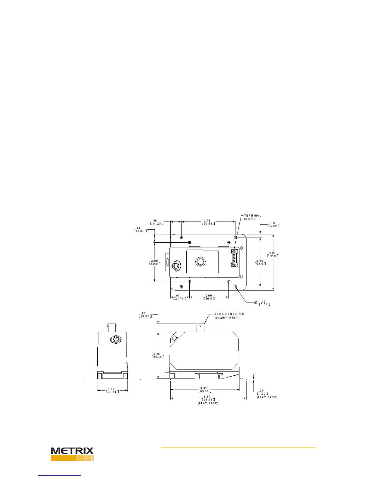
Driver / Transmier Installaon
Mount the driver or transmier in a suitable enclosure in a locaon that is compable with
its environmental specicaons. Refer to the datasheet for the environmental specicaons.
The driver or transmier comes as a DIN rail mount. The below gure shows the unit with
the oponal at base mounng plate, Metrix part number 9647. The 9647 mounng plate
has two dierent hole paerns. One is for Metrix 5465/5488 transmiers and the other pat-
tern is for Metrix 5533, MX3300 and most other manufacturers’ probe drivers.
Figure 8: Key dimensions for at base installaon.
 Loading...