Do you have a question about the Metro Therm METROAIR AQUA HPM and is the answer not in the manual?
| Brand | Metro Therm |
|---|---|
| Model | METROAIR AQUA HPM |
| Category | Heat Pump |
| Language | English |
Describes how the HPM is delivered, noting missing parts like drain tube and safety equipment.
Specifies conditions for storing the HPM, including temperature limits and upright position.
Details safe transport procedures using a forklift, ensuring the unit is in its designated box.
Instructions for safely unloading the heat pump, including tilting limitations.
Provides general information about the heat pump module design and EU guideline compliance.
Lists the items included in the product delivery, such as the unit, sensors, and manual.
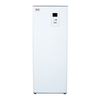
Describes the METROAIR AQUA HPM and its applications, including its components and automatic operation.
Explains how the METROAIR AQUA HPM operates, its typical usage for households, and auxiliary heater integration.
Lists detailed technical specifications of the heat pump module, including dimensions, weight, and operating ranges.
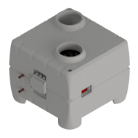
Explains the function and components of the refrigerant circuit, including the energy carrier and heat transfer process.
Outlines necessary standards, material compatibility, and safety requirements for the water circuit.
Shows the electrical wiring diagram for the Optima 172 controller and its connected components.
Graph illustrating fan performance curves based on air volume flow and static pressure.
Safety measures for the cooling system during service and repair, emphasizing fire prevention.
Rules and norms for connecting the unit to the power supply, including isolation distance.
Requirements for water quality and material compatibility in the circuit, including safety valve use.
Guidelines for safe usage by persons with reduced capabilities and children, emphasizing supervision.
Criteria for selecting an appropriate installation site for the HPM, including temperature and drain availability.
Step-by-step instructions for physically setting up the heat pump module, from unboxing to fixing.
Details on connecting the cold and hot water inlets/outlets, maximum pressure, and temperature.
Instructions for connecting the condensate drain pipe and water trap, ensuring a water seal.
Guide to connecting external sensors, pump, and optional electric heater in the junction box.
Procedure to check for leaks in the water installation and verify the condensate drain trap.
Steps for filling the water tank/system and deaerating the water circuit.
Checks to ensure air inlet and outlet paths are open and ready for use.
Describes the initial power-up sequence of the unit and controller display.
Introduction to the Optima 172 control panel, factory settings, and operational adjustments.
Explains how to navigate and change settings on the control panel using arrow keys.
Details the functions available in the main menu, including operating modes like Holiday and Automatic.
Instructions for accessing and navigating the service menu for advanced parameter settings.
Overview of sensor locations, relay outputs, and control feature operations.
Describes built-in safety mechanisms like high pressure switches and thermal protectors.
Explains alarm codes like PE (High pressure switch) and Er6 (Atypical evaporator temperatures).
Instructions for cleaning the evaporator and fan, emphasizing care for balancing weights.
Steps for cleaning the condensate tray and checking the drain for blockages.
Explains the function and regular maintenance of the pressure relief valve for tank protection.
Lists common checks for when the heat pump fails to supply hot water, covering power, water, and air flow.