Do you have a question about the Metro Therm SHK 200S and is the answer not in the manual?
Information regarding safety, important symbols, and product warnings.
Details on product marking, CE compliance, IP rating, and serial number location.
Guidelines for waste disposal of packaging and products, and installation acceptance checklist.
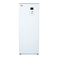
Instructions for transporting, assembling, and selecting an installation site for the indoor unit.
List of included items and step-by-step guide for removing the indoor unit's front cover.
Diagram illustrating the indoor module's components and a detailed legend for identification.
Recommendations for pipe installation, system flows, and general connection guidelines.
Information on the expansion vessel and minimum volume requirements for the heating system.
Basic connection diagram for the system and a table explaining various symbols used.
Diagram illustrating the connection scheme for an additional heat source.
Recommendations for indoor module installation and the suggested order of assembly steps.
Detailed layout of pipe connections, dimensions, and part numbers for system components.
List of compatible METROTHERM air/water heat pumps for the SHK 200S / SHK 200S-6 unit.
Instructions for connecting external heat sources like gas or oil boilers to the system.
Information on condensate elimination from the module and connecting refrigerant pipes.
Technical limitations regarding refrigerant pipe length and height difference for system connections.
Details on connecting to the heat pump, operating without one, hot/cold water, and additional heating circuits.
Specifications for pipe dimensions, materials, and minimum material thickness for copper pipes.
Guidelines for bending pipes, applying torque, and using appropriate tools for socket connections.
Specific installation notes for METROAIR L6, L8, and L12 models regarding pipe routing.
Procedures for conducting pressure and leakage tests on pipe connections after installation.
Instructions for using a vacuum pump to remove air from the system and achieve final pressure.
Guidance on insulating cooling medium pipes for thermal insulation and condensation prevention.
Information on filling the system with cooling medium, including quantities for different pipe lengths.
Table detailing connection parameters for METROTHERM SPLIT, including pressure, temperature, and flow rates.
Steps for connecting the DHW circulation pump and its control to the unit.
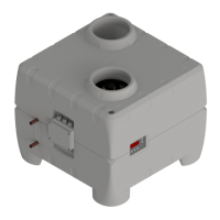
Guidelines for transporting, storing, and assembling the METROAIR L outdoor unit.
Instructions for placing the unit, lifting from the street, and lifting from the pallet.
Procedures for managing condensation water run-off and recommended alternatives for drainage.
Instructions on how to scrap the product by removing the bottom panel.
Detailed dimensions and drawings for the METROAIR L6 outdoor unit.
Detailed dimensions and drawings for the METROAIR L8 outdoor unit.
Detailed dimensions and drawings for the METROAIR L12 outdoor unit.
Recommendations for installation area, including minimum free space and placement considerations.
Information on sound power and sound pressure levels for different METROAIR L models.
General information regarding electrical connections, safety precautions, and cable requirements.
Diagram of indoor module connections and a legend for electrical components.
Details on the temperature limiter (FD1), its function, and how to reset it.
Information on cable blockade, power supply connection, and circuit breakers (FA1, FA2).
Instructions for electrically connecting the indoor unit (SHK) and outdoor unit (METROAIR L).
Guidance on connecting the external temperature sensor to the control unit.
Settings for the auxiliary preheater, emergency mode, and emergency mode thermostat.
Preparatory steps before starting the heat pump system, including switch position and valve checks.
Step-by-step guide for filling and venting the DHW heater and the heating system.
Procedure for emptying the heating system to facilitate servicing.
Information on the circulation pump's speed control and pressure characteristics.
Steps for initial start-up, commissioning, and using the start guide for system configuration.
Guidance on post-start regulation, including venting and addressing gurgling sounds.
Detailed explanation of operating within the start guide, including page navigation and help menus.
Instructions for operating the indoor unit as an electric boiler without an external heat pump.
Description of the display unit, including display, status lamp, buttons, and control knob.
Explanation of the SF1 switch positions: On, Standby, and Emergency mode.
Information on the USB port's location and its use for software updates.
Overview of the menu system structure, including main menus like Indoor Climate, Hot Water, Info, My System, and Service.
Explanation of various symbols that can appear on the display during operation.
How to operate the controller, navigate menus, select options, and set values.
Instructions for navigating the start guide and accessing the help menu for additional information.
Settings for indoor climate control, including temperature, ventilation, scheduling, and advanced options.
Settings for domestic hot water production, including temporary lux, comfort mode, scheduling, and advanced options.
Information menu providing access to service info, compressor data, additional heat info, alarm log, and indoor temperature log.
Configuration of system settings like plus functions, internet connection, operating mode, time/date, language, holiday setting, and advanced options.
Access to advanced service settings, operating settings, system settings, accessory settings, and forced control options.
Detailed breakdown of the start guide steps, covering language, information, climate system settings, accessories, sensors, and cooling.
Configuration of additional heat, slave devices, docking, time/date, flow temperatures, and heating curves.
Settings for operating modes, alarm actions, reminders, and selection for running the start guide again.
User-configurable settings for indoor climate, including temperature adjustments and scheduling.
Configuration of indoor climate scheduling and advanced settings like curves and external adjustments.
Advanced settings for climate control, including external adjustment, flow temperatures, and room sensor configuration.
Settings for cooling operation, curve offset adjustment, creating own curves, and hot water parameters.
Configuration of hot water comfort modes (economy, normal, luxury) and daily scheduling for hot water.
Advanced hot water settings, periodic increases, and access to system information like service, compressor, and heat info.
Access to alarm logs, indoor temperature logs, system information, and selection of operating modes (auto, manual, add. heat).
Configuration of system time, date, language, holiday settings, prioritization, and auto mode settings.
Resetting user settings, configuring degree minutes for heating control, and scheduling compressor blocking.
Important safety precautions for servicing and guidelines for replacing components with original spare parts.
Explanation of emergency mode, its activation, and the resulting system behavior.
Information on the USB service outlet for software updates, including the update process and important notes.
Options for choosing software files for updates and managing controller settings via USB memory.
How the control module indicates malfunctions using alarms, status lamps, and display messages.
Basic troubleshooting actions to check switches, fuses, and load monitors for operational interference.
Troubleshooting steps for low or no hot water, including checking valves, mixer settings, and operating modes.
Troubleshooting steps for heating issues, room temperature problems, and compressor start failures.
Guidance on using the 'add. heat only' mode to maintain heating while waiting for assistance.
List of accessories including room sensors, shunt groups, communication modules, and charge pumps.
Components for heat pump and hot water control, such as heat pumps, reversing valves, and relays.
Description of the Energy Measurement Kit (EMK 300) for measuring energy consumption.
Diagrams showing the dimensions and layout of connections for the indoor unit.
Table of technical specifications for SHK 200S/200S-6 and METROAIR L outdoor units.
Data on heating and cooling performance, including output, power consumption, and COP/EER.
Energy labelling information, including efficiency classes and data for space heating and water heating.
Detailed energy performance data for various METROAIR L models and their components.
Overall diagram showing external electrical connections for power and communication.
Connection diagrams for AA2 and AA27 PCA Base Input/Output modules.
Electrical diagram for the AA2 PCA Base Power supply and connections.
Connection diagram for the AA3 PCA Input module, showing sensor and auxiliary connections.
Connection diagram for the AA23 PCA Accessory module.
Electrical diagram for the AA7 relay card and related components.
Connection diagram for the AA8 PCA Titanium Anode and indicator light.
Diagram illustrating the main power connection to the unit, including circuit breakers and internal wiring.
Diagram showing the PCA Display module and its connections.
| Brand | Metro Therm |
|---|---|
| Model | SHK 200S |
| Category | Heat Pump |
| Language | English |