Do you have a question about the Meyer E-60 QUIK-LIFT and is the answer not in the manual?
Introduces general information, maintenance, and post-season maintenance topics.
Covers general upkeep, cleaning, and electrical system checks.
Covers fluid replacement, filter maintenance, and rust protection.
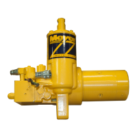
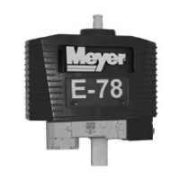
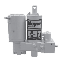
Details model identification, serial number location, and motor types.
Provides guidance on basic unit service, cleaning, and care.
Covers electrical system requirements and regular checks for the unit.
Details hydraulic fluid, filter maintenance, and protection against rust.
Covers general description, theory of operation, functions, and unit components.
Details unit mechanism, functions, and the Electro-Touch control system.
Illustrates electrical connections for the raise function.
Visualizes hydraulic fluid flow during the raise operation.
Shows electrical connections for lowering and float functions.
Visualizes hydraulic fluid flow during lower and float operations.
Illustrates electrical connections for angling the plow to the left.
Visualizes hydraulic fluid flow during the angle left operation.
Shows electrical connections for angling the plow to the right.
Visualizes hydraulic fluid flow during the angle right operation.
Describes motors, the hydraulic pump, and the pressure relief valve.
Explains solenoid valves, their components, and the roles of "A", "B", and "C" valves.
Explains the function of check valves and the crossover relief valve.
Details control switches, solenoid switch, and unit filters.
Covers general diagnostic information and essential testing procedures.
Provides guided steps for diagnosing common functional issues.
Provides general diagnostic information and essential testing procedures.
Guides the user through diagnosing why the snow plow will not raise.
Guides diagnosis for leak down and failure to lower issues.
Guides the user through diagnosing why the snow plow will not angle left.
Guides the user through diagnosing why the snow plow will not angle right.
Guides the user through diagnosing why the snow plow will not hold its angle.
Includes parts list, exploded view, component info, and special tools.
Covers procedures for taking apart and putting back together the main unit.
Details repair procedures for the pump, relief valve, and brushes.
Provides a comprehensive list of parts for E-60 and E-60H models.
Offers a detailed visual breakdown of unit components.
Provides guidelines and precautions for unit disassembly and reassembly.
Details the procedure for replacing the pump shaft seal.
Illustrates steps for removing the motor from the unit.
Illustrates steps for removing the pump assembly from the unit.
Illustrates steps for removing the unit's filters.
Illustrates removing adjustment screws and pressure relief parts.
Illustrates steps for removing the "A" Solenoid Cartridge.
Illustrates removing pressure relief parts, coils, and "B" cartridge.
Illustrates steps for removing "B" and "C" Solenoid Cartridges.
Illustrates steps for removing "C" cartridge, pilot valve plug, and valve body.
Illustrates removing pilot valve parts and extending the ram.
Illustrates removing the top cap, ram/cylinder, and cylinder tank.
Illustrates installing the lift cylinder O-ring and studs.
Illustrates cleaning the ram and sliding the cylinder over it.
Illustrates installing the washer, top cap seal, and reservoir.
Illustrates removing the acorn nut and plug from the crossover relief valve.
Illustrates removing the plug, adjusting screw, disc, and spring.
Illustrates removing internal parts of the crossover relief valve.
Illustrates reinstalling O-rings and the cage into the valve.
Illustrates assembling the poppet with bushing into the cage.
Illustrates assembling the washer, bushing, and cage with the poppet.
Illustrates sliding the O-ring and dropping the cage assembly.
Illustrates reassembling the washer and spacer.
Illustrates reassembling the spring guide and spring.
Illustrates reassembling the plug, adjusting screw, disc, and O-ring.
Illustrates installing O-rings in the sump base and the P.A. block assembly.
Illustrates installing the pressure relief valve and adjustment screw.
Illustrates installing the locator pin and pump check valve.
Illustrates installing the pump mounting plate.
Illustrates installing the pump and torquing mounting bolts.
Illustrates installing the motor mounting cover.
Illustrates installing the motor and torquing cap screws.
Illustrates installing different motor types and torquing bolts.
Illustrates installing the Fenner motor cover correctly.
Details the procedure for replacing brushes on an Iskra motor.
Details the procedure for replacing brushes on a Fenner motor.
Identifies the special tool required for "B" and "C" cartridges.
Identifies the special tool for the pump check valve.
Lists voltage, current draw, and resistance for motors and solenoids.
Lists pressure outputs for pumps and crossover relief valves.
Details fluid capacity for E-60 and E-60H models.
Lists torque values for various fasteners and assemblies.
| Model | E-60 QUIK-LIFT |
|---|---|
| Category | Portable Generator |
| Voltage | 120/240V |
| Frequency | 60 Hz |
| Wheels | Yes |
| Transfer Switch Ready | Yes |
| Sound Level | 74 dBA at 23 ft |
| Warranty | 2 years |