Do you have a question about the Meyer ELECTRO LIFT E-46 and is the answer not in the manual?
Basic information about the Electro Lift® unit, including model and serial number identification.
Details on general maintenance, cleanliness, and electrical system checks.
Procedures for post-season care, fluid replacement, and rust protection.
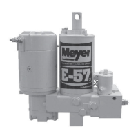
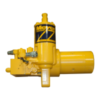
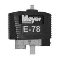
Details on identifying different Electro Lift® models and their features.
How to identify the brand and type of motor used in the units.
Requirements for the vehicle's electrical system for optimal unit performance.
Items to regularly check for proper operation and safety.
Overview of the Electro Lift® unit, its components, and capabilities.
Explains how the Electro Lift® unit functions in various operations.
Describes the basic functions performed by different Electro Lift® models.
Specific functions for E-46 and E-46H models, focusing on lift and lower.
Specific functions for E-47/E-57 models, including angling.
Details on the different types of motors used in Electro Lift® units.
Explains the function and operation of the hydraulic pump.
Description and function of the pressure relief valve.
Explains the purpose, components, and types of solenoid valves.
Details on the "A" solenoid valve and its function.
Details on the "B" solenoid valve and its function.
Details on the "C" solenoid valve and its function.
Explains the function and types of check valves used in the system.
Details on the pilot check valve and its functions.
Explains the function of the crossover relief valve.
Describes the single toggle switch for E-46/E-46H models.
Describes the control switches for power angling models.
Explains the function and operation of the solenoid switch.
Details the filter system used in Electro Lift® units for reliability.
Pre-troubleshooting checks and conditions required for accurate diagnosis.
Important tips and techniques for testing Electro Lift® unit components.
Diagnostic flow chart for issues related to the raise function.
Diagnostic flow chart for problems where the unit leaks down.
Diagnostic flow chart for issues when the unit will not lower.
Diagnostic flow chart for problems with the angle left function.
Diagnostic flow chart for problems with the angle right function.
Diagnostic flow chart for issues where the angle is not held.
Guidelines and precautions for unit disassembly and reassembly.
Step-by-step procedures for taking apart and reassembling the unit.
Information related to the hydraulic pump, including shaft seal replacement.
Procedure for replacing the pump shaft seal.
An exploded diagram of the Electro Lift® unit for parts identification.
A list of all parts for the Electro Lift® units.
Visual guide for disassembling various Electro Lift® components.
Visual guide for reassembling various Electro Lift® components.
Information regarding the crossover relief valve.
Procedures for replacing motor brushes.
Details on servicing the "A", "B", and "C" valve cartridges.
A detailed list of all available parts for the Electro Lift® units.
Step-by-step visual guide for disassembling all Electro Lift® models.
Specific disassembly steps for E-47 and E-57 models.
Further disassembly steps for E-47 and E-57 models.
Step-by-step visual guide for reassembling all Electro Lift® models.
Procedure for disassembling the crossover relief valve.
Procedure for reassembling the crossover relief valve.
Step-by-step instructions for replacing brushes on the American Bosch motor.
Instructions for replacing brushes on the Iskra motor.
Detailed steps for American Bosch motor brush replacement.
Detailed steps for Iskra motor brush replacement.
Details on disassembling and servicing the "A", "B", and "C" valve cartridges.
Details on the specific tool required for "B" and "C" cartridge removal.
Information on the tool used for crossover relief valve adjustment.
Information about the specialized tool for American Bosch motor brush replacement.
Electrical ratings and parameters for motors, switches, and solenoids.
Specific electrical details and operating parameters for the unit's motors.
Electrical specifications relevant to the solenoid switch.
Pressure output, capacity, and fluid specifications for the hydraulic system.
Recommended torque values for various fasteners and assembly points.
| Brand | Meyer |
|---|---|
| Model | ELECTRO LIFT E-46 |
| Category | Portable Generator |
| Language | English |