ELECTRO LIFT® UNIT COMPONENTS CONT.
CHECK VALVES
Check valves are very simple devices that have two
basic functions: They prevent fluid from passing through
them in one direction, but they allow fluid to pass
through them in the opposite direction.
In all four Power Angling models a pump check valve
is used to prevent hydraulic fluid from leaking back
through the pump to the reservoir. Its function on the
E-46 and E-46H models is more critical since it is the
only means by which pressurized hydraulic fluid
pumped into the lift cylinder is prevented from leaking
out through the pump, causing the plow to slowly come
down.
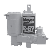
The E-47 and E-57 models incorporate two additional
check valves, necessary because the “B” and “C”
Solenoid Valves, being spool valves, have some
leakage.
One check valve is located between the “B” Solenoid
Valve and the lift cylinder. It prevents the hydraulic fluid
in the lift cylinder from leaking back through the “B”
Solenoid Valve which could cause the weight of the
plow to angle the plow to the left by forcing hydraulic
fluid through the “C” Solenoid Valve into the right power
angling cylinder.
The other check valve is located between the “B” and
“C” Solenoid Valves. It prevents the hydraulic fluid in
either power angling cylinder from being forced
through the “B” Solenoid Valve to the left cylinder.
PILOT CHECK VALVE
The pilot check valve is more sophisticated in that it
incorporates a piston in addition to the ball, seat and
spring. It is located between the “C” Solenoid Valve
and reservoir. It has two functions: The first is to prevent
the hydraulic fluid in either power angling cylinder from
leaking back to the reservoir. The second is to allow
the hydraulic fluid from the retracting power angling
cylinder during the angling cycle to return to the
reservoir. This is accomplished by the pressurized
hydraulic fluid moving the piston which forces the check
ball off its seat.
CROSSOVER RELIEF VALVE
When plowing snow, a snow plow can be exposed to
damaging forces caused by impact with hidden
obstructions, ends of curbs, etc. With power angling,
these damaging forces can damage not only the snow
plow but also the vehicle. The crossover relief valve
has the function of protecting the snow plow system
against these damaging forces under normal snow
plowing conditions. The crossover relief valve, cannot
protect the system from damaging forces that are too
great due to abusive snow plowing conditions.
Basically, the crossover relief valve functions exactly
like the previously described pump relief valve. It’s
designed to open at a specific pressure.
In this instance, the pressure is not produced by
the pump but rather by the damaging force. As an
example, assume that the right corner of the plow
runs into the end of a curb. The impact will attempt
to collapse the right power angling cylinder. As a
result, very high hydraulic pressure is produced
within the cylinder. When the produced pressure is
high enough, it opens the crossover relief valve,
allowing the highly pressurized hydraulic fluid to
flow directly to the left power angling cylinder.
When the crossover relief valve functions in this
manner, the excessive pressure is released, the
excessive energy produced by the impact is
absorbed, and the result is only a change in angled
position of the plow.
The crossover relief valve may be adjusted to the
specified pressure of 3800 P.S.I. ± 400 by turning the
3/8” hex cap screw after installing a suitable pressure
gauge of 4000 P.S.I. in the circuit. TIGHTEN (TURN IN)
ADJUSTMENT SCREW TO INCREASE PRESSURE.
See Figure 3-63. Disassembly/ Reassembly figures
3-42 thru 3-62.
SWITCH
(Models E-46 and E-46H)
A single three-position toggle switch Is used on the
E-46 and E-46H models. The positions are:
• Off (Center Position)
• Raise (Up Position)
• Lower and Float (Down Position)
In the “off” position, the switch conveys no current.
In the “raise” position, the switch conveys current to
the solenoid switch. When released, an internal spring
returns the toggle to the “off” position.
In the “lower and float” position, the switch conveys
current to the “A” Solenoid Valve. When released, the
toggle will stay in the “lower and float” position. The
toggle must be manually returned to the “off”
position.
SWITCHES (Power Angling Models)
Dual Switch Control
Two three-position toggle switches are used on the
E-47 and E-47H models. The first, to raise and lower
the plow, has the same positions as the toggle switch
used on the E-46 and E-46 H models. However,
because it functions differently, it is a completely
different switch.
In the “off” position, the switch conveys no current.
In the “raise” position, the switch conveys current
to the solenoid switch and the “B” Solenoid Valve.
When released, an internal spring returns the toggle
to the “off” position.
-21-