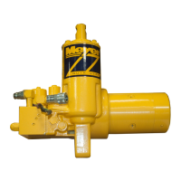
FIGURE 3-50
Reinstall O-ring (48) making certain it is seated to the
bottom of the cavity.
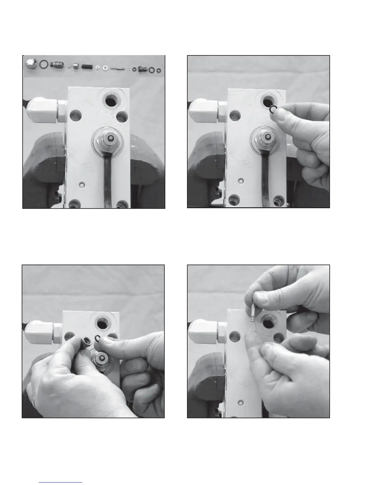
FIGURE 3-51
Install small O-ring (51) into top of cage (50).
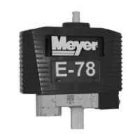
FIGURE 3-52
Install small bushing (51) onto poppet (52).
CROSSOVER RELIEF VALVE REASSEMBLY
-46-
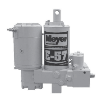
FIGURE 3-49
Correct order when reassembling Crossover Relief Valve
(47). Note: All parts should be dipped in oil prior to their
assembly.