ELECTRO LIFT® UNIT COMPONENTS CONT.
SWITCHES (Power Angling Models) Cont.
Dual Switch Control
The second toggle switch is to angle the plow. The
positions are:
•Off (Center Position)
•Angle Left (Left Position)
•Angle Right (Right Position)
In the “off” position, the switch conveys no current.
In the “angle left” position, the switch conveys
current to the solenoid switch. When released, an
internal spring returns the toggle to the “off”
position.
In the “angle right” position, the switch conveys
current to the solenoid switch and to the “C”
Solenoid Valve. When released, an internal spring
returns the toggle to the “off” position.
Single Lever Control
A single lever control is also used on the Electro
Lift
®
models. This switch (five-position) functions the
same as the two three-position toggle switches
previously discussed.
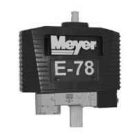
Electro-Touch
®
Control Pad
IMPORTANT:
The power lead to the switch should be connected
to a terminal on the fuse panel that is HOT ONLY
when the ignition switch is in the “ON” position.
When the control switch is powered up, yellow lights
illuminate the arrows of the individual functions. The
up arrow for raise, the left arrow for angle left, the
right arrow for angle right and the down arrow for
lower or float.
Holding the down arrow for a full second will activate
a light located in the upper left corner of the
Electro-Touch
®
switch. This light indicates the snow
plow is now in the float position. In this position the
snow plow will be able to follow the contour of the
road and the snow plow can also be angled to the
left or right. Touching the up arrow will automatically
cancel the float position.
This switch is short circuit, open circuit and
temperature protected. If any of these conditions
exists, the overload light will illuminate. The overload
light is located just below the float light in the upper
left corner of the Touch Pad. Reset is accomplished
by cycling the power to the Touch Pad via the on/
off switch located to the left of the cord as it enters
the Touch Pad.
CAUTION: When the snow plow is not in operation,
the Electro-Touch
®
Control Switch should be in the
“OFF” position.
SOLENOID SWITCH
The Electro Lift
®
motor requires more current or
amperage to operate than the vehicle wiring, vehicle
ignition switch or toggle switches have the capacity
to handle. The solenoid switch is essentially a heavy
duty switch with the capacity to handle the heavy
current required by the motor. It is closed electrically
by the solenoid to convey the heavy current directly
from the vehicle battery via heavy gauge electrical
cable. The solenoid, which functions essentially the
same as the previously described solenoid valves,
receives its low amperage current at the proper
times via the wiring harness. This solenoid must be
grounded to operate properly.
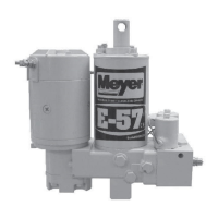
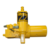
FILTERS
Cleanliness is perhaps the single most important
ingredient in assuring a hydraulic system’s reliability.
Should the hydraulic fluid become contaminated,
malfunction and permanent damage to the
hydraulic system may occur. For this reason, all
the Electro Lift
®
units are equipped with a filter
system consisting of:
E-46 E-47, E-57
E-46H E-47H, E-57H
X X A fine screen strainer on the
reservoir pump inlet.
X X A filter screen between the lift
cylinder and “A” Solenoid Valve.
X A high pressure filter on the pressure
side of the pump.
With this system, the hydraulic fluid is filtered as it
leaves the reservoir on its way to the pump and on the
Power Angling units filtered again as it leaves the
pump. Because clean hydraulic fluid is most
important to insure “A” Solenoid Valve reliability, the
hydraulic fluid leaving the lift cylinder is filtered
before passing through the “A” Solenoid Valve. The
filter screen and high pressure filter are easily
removed for periodic cleaning or replacement.
NOTE: Additional filter screens are added to the
“A”, “B” and “C” Cartridge Valves.
IMPORTANT:
Should the hydraulic fluid become contaminated,
it will be necessary to replace all the hydraulic oil in
the system. The complete system (hydraulic unit,
power angling cylinders and hoses) should be
flushed. Flush the system with Meyer Hydra-Flush™
Fluid M-2.
-22-