DETACHING THE COMPLETE ASSEMBLY
Leave control switch in lower float position and push down on the Lift Arm.
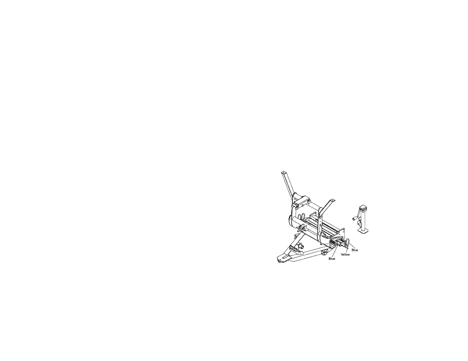
Disconnect the electrical plug and slip on weather caps over the both ends.
Attach Crankstand to the adjustment tube in the center of the A-Frame using
the chained locking pin. Caution: Crankstand must be secured at all times.
Adjust the Crankstand down until the bottom of stand touches the ground.
Pull and twist the two rear Blue Handle Pins to disengage. Next pull and
twist the two front Blue Handle Pins to disengage. If the pins do not pull
easily, adjust stand up or down slightly to remove tension on the pins until
they disengage. At this time the lift frame should be leaning forward slightly,
at rest on the top of the Crankstand. Pull truck away.
DETACHING MOLDBOARD ASSEMBLY ONLY
Leave control switch in lower float position and push down on the Lift Arm.
Disconnect hydraulic couplers and Lift Chain from Lift Arm. Attach Crankstand
to the adjustment tube in the center of the A-Frame using the chained locking
pin. Caution: Crankstand must be secured at all times. Adjust the
Crankstand down until the bottom of stand touches the ground. Pull and
twist the Yellow Handled Pins to disengage. If the pins do not pull easily,
adjust stand up or down slightly to remove tension on the pins until they
disengage. Pull truck away.
ATTACHING THE COMPLETE ASSEMBLY
Check that all four Blue Handle Pins are disengaged. Drive the truck up to
the MDII assembly centering the hood of the truck to the lift arm to assure
proper alignment with lift frame guide plates until contact is made. Once
contact is made drive forward, pushing the assembly a few inches. This
insures the A-Frame is square to the Clevis Frame for proper pin attachment.
Adjust the Crankstand up until the front of the truck raises slightly. The rear
Blue Handle Pins should now be aligned with the rear holes on the clevis
frame. Twist all Blue Handle Pins so that the small leg re-aligns with the slot,
engaging the pins. The rear spring loaded pins should snap into place. Note:
If pins do not lock immediately the A-Frame is not square to the Clevis Frame.
Move truck slightly forward and/or adjust the Crankstand up or down until
rear pins engage. Once the back pins are locked push the top of the Lift
Frame towards the truck locking the front pins to the clevis frame. Remove
the Crankstand from the A-frame by removing the chained locking pin.
Reattach the Crankstand to the transport tube on the driver’s side of the Lift
Frame in the vertical, retracted position. Caution: Crankstand must be
secured at all times. Reattach the one step electrical connection.
5