EasyManua.ls Logo

MFJ Enterprises Grandmaster MFJ-484 - User Manual

MFJ Enterprises Grandmaster MFJ-484
6 pages
Print Icon
To Next Page IconTo Next Page
Loading...
Question and Answer IconNeed help?

Do you have a question about the MFJ Enterprises Grandmaster MFJ-484 and is the answer not in the manual?

Summary

Control Functions

Speed Control

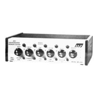
Adjusts keying speed from 8 to 50 wpm. Pull out to record.

Weight Control

Sets dot-dash-space ratio. Pull out to combine memory addresses A and B.

Tone Control

Adjusts side tone pitch. Pull out to tune transmitter.

Volume Control

Adjusts internal speaker loudness. Turn fully counter-clockwise to turn off.

Delay Control

Enables automatic message repetition with variable delay. Pull out to activate.

Memory Select

Selects memory banks (1, 2, 3, K) for recording and playback.

Memory Address

Buttons A, B, C, D to directly address memory locations for recording/playback.

Reset

Stops memory operation. Can also be interrupted by tapping the paddle.

LED Indicators

Show active memory address (A-D) and time delay status.

Memory Saver

Internal 9V battery retains memory during AC power failure.

Installation

Operating Procedure

Keyer Operation

Basic steps for using the keyer, including power-up and paddle connection.

Memory Operation

Detailed instructions for recording and playing back stored messages.

Memory Recording

Steps and considerations for recording messages into memory addresses.

Memory Playback

Instructions for playing back recorded messages and repeating them.

Operation Notes

Important considerations for RF interference, battery saving, and adapter use.

Overview

The MFJ-484 Grandmaster Memory Keyer is a sophisticated electronic device designed for amateur radio operators, utilizing 15 state-of-the-art Integrated Circuits and 4 Random Access Memories to provide advanced keying capabilities.

Function Description

The primary function of the MFJ-484 is to assist in sending Morse code by providing memory storage for messages and automating keying operations. It acts as an interface between a keyer paddle and a transmitter, allowing for precise and flexible control over Morse code transmission. The device supports both iambic and single-lever keying, enhancing the operator's sending efficiency and accuracy.

Important Technical Specifications

  • Speed Control: Variable from 8 to 50 words per minute (wpm).
  • Memory Capacity:
    • Each of the three MEMORY SELECT positions (1, 2, 3) has four MEMORY ADDRESSES (A, B, C, D), each capable of storing up to 25 characters. This allows for a total of twelve 25-character messages.
    • Combining MEMORY ADDRESSES A and B (by pulling out the WEIGHT CONTROL) doubles the memory space for those addresses.
    • MEMORY SELECT position K automatically combines A, B, C, and D for recording very long messages, offering 100, 75, 50, or 25 characters respectively, depending on which address button (A, B, C, or D) is pressed.
  • Time Delay: Variable from 0 to 2 minutes for automatic message repetition.
  • Power Requirements:
    • Operates with a supplied 110-volt AC adapter.
    • External battery input: 12-15 VDC (sub-miniature jack, tip positive, sleeve ground).
    • Internal Memory Saver battery: 9-volt alkaline battery (not included, recommended type). Provides approximately three hours of operation if the side tone is not used during AC power failure.
  • Keyer Outputs:
    • GRID BLOCK Keying Output: Keys a maximum negative voltage of 300 volts to ground at 10 mA.
    • DIRECT Keying Output: Keys a maximum positive voltage of 300 volts to ground at 100 mA.
    • Both outputs are self-protected.
  • Paddle Input: Standard quarter-inch stereo phone jack for dual paddle squeeze key or single lever key.

Usage Features

  • SPEED CONTROL: Adjusts sending speed. Pulling it out activates record mode.
  • WEIGHT CONTROL: Adjusts the dot-dash-space ratio. Fully counter-clockwise sets a perfect 1:3:1 ratio. Turning clockwise increases dot and dash lengths. Pulling it out combines A and B memory addresses for increased storage.
  • TONE CONTROL: Adjusts the side tone pitch. Pulling it out activates TUNE mode, continuously keying the transmitter.
  • VOLUME CONTROL: Adjusts the loudness of the internal speaker. Turning it fully counter-clockwise turns off the keyer and erases all stored messages.
  • DELAY CONTROL: Pulling it out activates the time DELAY function for automatic message repetition. The delay time is variable. Turning it fully counter-clockwise results in instant repetition.
  • MEMORY SELECT: A rotary switch with positions 1, 2, 3, and K, used to select memory banks for recording and playback.
  • MEMORY ADDRESS Buttons (A, B, C, D): Used to directly address specific memory locations for starting or recording messages.
  • RESET Button: Stops memory operation. Can interrupt a message being sent or a time delay cycle.
  • LED INDICATORS: LEDs for A, B, C, and D light up to show which memory address is in operation. A fifth LED indicates the time delay period.
  • Dot and Dash Memories: Eases sending by allowing keying of a dot before a dash completes, or vice versa. This feature enables dot insertion (tapping dot side while holding dash) and dash insertion (tapping dash side while holding dot).
  • Iambic Operation: When using a squeeze key, squeezing both paddles simultaneously sends alternating dots and dashes. The first contact determines whether a dot or dash occurs first.
  • Recording Procedure:
    1. Select a MEMORY SELECT position (1, 2, 3, or K).
    2. Pull out the SPEED control and adjust speed.
    3. Press a MEMORY ADDRESS button (A, B, C, or D) and immediately begin sending. The corresponding LED will light during recording. The LED turning off indicates the memory is full.
    4. Spaces of any length can be recorded as the internal clock runs continuously.
    5. To ensure a complete erase of previous messages, press the address button two or three times before sending a new message.
    6. The keyer keys the transmitter in recording mode, so it must be disconnected or the transmitter disabled during recording.
  • Playback Procedure:
    1. Push in the SPEED control to enter play mode.
    2. Press the desired MEMORY ADDRESS button. The corresponding LED indicates which memory is in operation.
    3. To interrupt a message or make an insertion, simply send with the paddle. The message can be continued by pressing another MEMORY ADDRESS button.
    4. To repeat a message, pull out the DELAY control. Adjust the control clockwise for longer delays.

Maintenance Features

  • Memory Saver: An internal 9-volt battery (alkaline type recommended) automatically activates during AC power failure to retain all stored messages. The battery clip and holder are provided for easy installation. The MEMORY SAVER is turned off when the VOLUME CONTROL is turned off.
  • Installation of Memory Save Battery:
    1. Remove two screws near the rear top of the device.
    2. Slide the cover toward the back.
    3. Connect a 9-volt battery to the battery snap and insert it into the holder.
    4. If the battery is not used, cover the battery snap with the supplied plastic tubing to prevent shorting.
  • Cable Shielding: Shielded cables must be used between the memory keyer jack and paddle, and between the keyer output and the transmitter, to prevent RF interference.
  • Power Adapter: Only the supplied MFJ AC ADAPTER should be used. For external batteries, do not exceed 15 volts.

MFJ Enterprises Grandmaster MFJ-484 Specifications

General IconGeneral
BrandMFJ Enterprises
ModelGrandmaster MFJ-484
CategoryRadio
LanguageEnglish