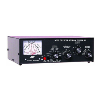
MFJ-948 Versa Tuner II
2
In the 30W position the forward power scale must be divided by 10. Each picket
represents 1/2 watt below 1 watt, 1 watt from 1 to 10 watts, and 2.5 watts from 10 to 30
watts.
The reflected power is read on the right-hand REFLECTED meter scale. This scale
indicates 60 watts full scale when the 300W power sensitivity is selected, and 6 watts full
scale when the 30W power scale is selected. This scale has a picket every 5 watts above 10
watts and at each watt below 10 watts. This scale is also divided by 10 when using the
30W switch position.
When trying to measure power with a less than perfect match, the reflected power should
be subtracted from the forward power readings. The most accurate peak power readings
are obtained only with a sustained carrier, voice or two tone test modulation. During
normal voice modulation the wattmeter will typically indicate 70% of the true peak power.
The SWR is read directly from eleven red SWR curves that range from 1:1 to infinity.
SWR is measured by observing the point where the forward and reflected power needles
cross. The SWR is indicated by the red curve closest to the needle crossing point. No
cumbersome or time consuming SWR sensitivity adjustments are required with this meter.
The wattmeter has an internal lamp that backlights the meter scale. The lamp circuit
requires power from an external 12 Vdc source, such as the optional MFJ-1312C power
supply. The rear panel jack accepts a 2.5 mm coaxial plug with a positive center pin
polarity. The METER LAMP ON / OFF switch turns the meter lamp off and on.
Antenna Selector
The ANTENNA SELECTOR switch has eight positions. From counter-clockwise to
clockwise the positions are: EXT. DUMMY LOAD, BALANCED or SINGLE WIRE
LINE, COAX 1, and COAX 2 with the tuner matching circuits in line, and the reverse
sequence from COAX 2 back to EXT. DUMMY LOAD with the antenna tuning circuits
bypassed.
NOTE: An external 50 ohm dummy load should be connected to the tuner when the
ANTENNA SELECTOR switch is in the EXT. DUMMY LOAD position.
Downloaded from www.g7syw.com
 Loading...