Do you have a question about the MFJ Enterprises MFJ-948 and is the answer not in the manual?
Describes the cross-needle meter for forward/reflected power and SWR measurements.
Warns about high RF voltages on rear terminals and the risk of burns or damage.
Provides instructions for connecting the transmitter, coaxial feedlines, and wire antennas.
Explains the function of the "T" network, capacitance, and inductance controls.
Covers tuning the transmitter output and using the bypass function.
Presents the tuning chart and initial steps for setting controls by frequency.
Details how to adjust TRANSMITTER and ANTENNA MATCHING for lowest SWR.
Guidance on increasing transmitter power once low SWR is achieved.
Advice for troubleshooting tuner arcing at rated power levels.
General advice for when the tuner fails to tune or operates improperly.
Explains the importance and methods for effective RF and lightning grounding.
Recommendations for antenna location and specific configurations for optimal performance.
Emphasizes connecting a good earth ground for operator safety.
Explains how feedline and antenna lengths can cause matching difficulties.
Offers suggestions to reduce complexity when matching antennas.
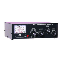
The MFJ-948 Versa Tuner II is a versatile antenna tuner designed to match a wide range of transmitters and transceivers to virtually any antenna system. It functions as a 300-watt RF output power antenna tuner, capable of handling both peak and average forward and reflected power, as well as SWR, which are displayed on an illuminated cross-needle meter.
At its core, the MFJ-948 utilizes a "T" matching network, allowing it to cover all amateur bands from 160 to 10 meters. This network is highly adaptable, capable of tuning various antenna types including dipoles, inverted-vees, verticals, mobile whips, beams, random wires, and many other configurations. The tuner provides rear panel connectors for coaxial, single-wire, or two-wire feedlines. A key feature is its built-in 4:1 balun, which enables the use of balanced feedlines such as open wire, twinlead, or twin-axial lines.
An internal eight-position antenna-selector switch enhances the tuner's flexibility. This switch allows users to select between an external 50-ohm dummy load, two separate coaxial line outputs, or a single-wire/balanced-line output. Each of these options can be used in either a "tuned" configuration, where the tuner's "T" network is engaged, or a "bypassed" configuration, where the tuning circuit is disengaged.
The integrated peak-reading SWR/Wattmeter is a crucial component for monitoring antenna system performance. This illuminated cross-needle meter displays peak or average FORWARD power, REFLECTED power, and SWR. The wattmeter is active across all ANTENNA SELECTOR positions. For power measurement without the tuning circuit, users can select one of the ANTENNA SELECTOR positions under BYPASS.
The MFJ-948 offers intuitive controls for power measurement. The left METER switch allows selection between a 300W and a 30W full-scale range for forward and reflected power. For transmitters exceeding 30 watts, the 300W position (in) should be selected; for transmitters with less than 30 watts, the 30W position (out) is appropriate.
Peak envelope power (PEP) is measured by placing the PEAK or AVERAGE METER push button (on the right-hand side) in the PEAK (in) position. It's important to note that peak and average power values are equal for steady unmodulated carriers, FSK, or FM. PEP power is typically twice the average power with SSB two-tone test modulation and can be even higher with SSB voice signals.
Forward power is displayed on the left-hand FORWARD meter scale, calibrated from 0 to 300 watts. In the 300-watt position, the scale is read directly, with each mark representing 25 watts between 300 and 100 watts, 10 watts between 100 and 10 watts, and a single 5-watt mark below 10 watts. When operating in the 30W position, the forward power scale must be divided by 10. In this mode, each mark represents 1/2 watt below 1 watt, 1 watt from 1 to 10 watts, and 2.5 watts from 10 to 30 watts.
Reflected power is read on the right-hand REFLECTED meter scale. This scale indicates 60 watts full scale when the 300W power sensitivity is selected, and 6 watts full scale when the 30W power scale is selected. This scale has a mark every 5 watts above 10 watts and at each watt below 10 watts, and is also divided by 10 when using the 30W switch position. When the antenna match is less than perfect, reflected power should be subtracted from forward power readings for accurate power measurement. The most accurate peak power readings are achieved with a sustained carrier, voice, or two-tone test modulation. During normal voice modulation, the wattmeter typically indicates about 70% of the true peak power.
SWR is read directly from eleven red SWR curves ranging from 1:1 to infinity. SWR is determined by observing the point where the forward and reflected power needles cross, with the SWR indicated by the red curve closest to the crossing point. This design eliminates the need for cumbersome SWR sensitivity adjustments.
The wattmeter includes an internal lamp for backlighting the meter scale, requiring an external 12 Vdc source (e.g., MFJ-1312C power supply) connected via a 2.5 mm coaxial plug with positive center pin polarity. The METER LAMP ON/OFF switch controls the lamp.
The ANTENNA SELECTOR switch has eight positions, arranged counter-clockwise to clockwise: EXT. DUMMY LOAD, BALANCED or SINGLE WIRE LINE, COAX 1, and COAX 2 (with tuner matching circuits in line), followed by the reverse sequence from COAX 2 back to EXT. DUMMY LOAD (with antenna tuning circuits bypassed). An external 50-ohm dummy load should be connected when the ANTENNA SELECTOR switch is in the EXT. DUMMY LOAD position.
Installation involves placing the tuner in a convenient operating location, away from RF-sensitive devices. It connects between the transmitter and antenna via a 50-ohm coaxial cable to the TRANSMITTER SO-239 connector. Coaxial feedlines attach to COAX 1 and COAX 2 SO-239 connectors. A random wire antenna connects to the WIRE binding post. Balanced feedlines connect to the BALANCED LINE binding posts, with a jumper wire from the WIRE binding post to one of the BALANCED LINE posts activating the internal 4:1 balun. It's crucial not to connect wire and balanced antennas simultaneously unless intended.
When using the MFJ-948, it's advised never to change the ANTENNA or INDUCTOR selector switch position while transmitting, and never to apply more than 300 Watts. For optimal power handling and smooth tuning, the TRANSMITTER and ANTENNA MATCHING controls should use the highest possible capacitance for each band (position 0 is maximum capacitance, 10 is minimum). The INDUCTANCE switch has maximum inductance at "A" and minimum at "L"; less inductance is needed for higher frequencies.
Tuning involves setting the METER switch to 30W (out), PEAK AVG button to AVG (out), and turning down transmitter power. Initial settings for TRANSMITTER, ANTENNA MATCHING, and INDUCTOR SELECTOR can be referenced from the tuning chart. Apply minimal CW, AM, FM, or RTTY power to get a reflected power deflection, then carefully adjust TRANSMITTER and ANTENNA MATCHING for the lowest reflected power. These controls interact, requiring iterative adjustment. If a low SWR isn't achieved, try different INDUCTOR switch settings, always using the lowest alphabetical setting possible. Once a low SWR is obtained, transmitter power can be increased up to 300 watts carrier or PEP.
For safety and optimal performance, good grounding practices are emphasized. Both DC and RF grounds should be used, especially with single-wire feeders. A good RF ground is essential to prevent RF from finding its way into power lines, audio circuits, or causing RF burns to the operator. Water pipes, heating ducts, and fences can serve as grounds, but radial systems or multi-wire counterpoises are recommended for the best RF grounds. Ground leads for RF and lightning should have wide, smooth surfaces, avoiding braided or woven conductors unless flexibility is required.
A critical safety warning states that a good outside earth ground or water pipe ground should ALWAYS be installed and connected to the case of the MFJ-948, ensuring it also connects to the transmitter and other station accessories via the GROUND wing nut post.
The manual also provides troubleshooting advice for matching problems, particularly those arising from antenna and feedline lengths creating extremely high impedances at the tuner. It suggests avoiding certain feedline lengths and configurations that can lead to difficult-to-tune scenarios, such as odd quarter-wavelength feedlines with half-wave multi-band antennas or half-wave feedlines with full-wave antennas. If tuning issues persist, adding or subtracting 1/8 wave of feedline or adjusting antenna length is recommended.
For 160-meter operation with 80 or 40-meter antennas, it's advised to load either or both feedline wires in parallel as a longwire, effectively making the antenna act like a "T" antenna against the station ground, to avoid extreme reactivity.
Technical assistance is available via phone, mail, FAX, or email, with technicians requiring detailed information about the unit, manual, and station setup for effective support.
| Type | Antenna Tuner |
|---|---|
| Frequency Range | 1.8-30 MHz |
| Impedance | 50 Ohms |
| Tuning Method | Manual |
| Antenna Switch | Yes |
| Power Rating | 300 W PEP |
| Meter | Built-in SWR/Wattmeter |
| Power Handling | 300 W PEP, 150 W continuous |